Configuration Number |
Location Number |
Name |
Default Value |
Description |
C000 |
L010 |
Off-Peak Method of Charge Control |
5 |
Sets the method of brick core charging to be used during off-peak (charge) periods. System is configured for automatic charge control which is a value of five (5). |
C001 |
L012 |
Start Brick Core Charge Set Point |
50°F |
If utilizing automatic charge control as set in C000, this value indicates the outdoor temperature at which the system will start charging. |
C002 |
L013 |
Full Brick Core Charge Set Point |
10°F |
If utilizing automatic charge control as set in C000, this value indicates the outdoor temperature at which the system will target a full core charge. |
C003 |
L020 |
Power Line Carrier (PLC) Channel Selection |
0 |
If using PLC communication, this setting must match the channel setting in the Steffes PLC transmitting device. A value of zero indicates power line carrier communication is disabled. |
C004 |
L035 |
Optional Controls Configuration |
9 |
Notifies the unit when Time Clock Module or Outdoor Sensor are being utilized.
Value |
Configuration Description |
|
8
|
No Outdoor Sensor/No Time Clock Module
|
|
9
|
Outdoor Sensor/No Time Clock Module
|
|
12
|
No Outdoor Sensor/Time Clock Module |
|
13
|
Outdoor Sensor/Time Clock Module |
|
C005 |
L036 |
Control Switch Configuration |
1 |
If utilizing power line carrier control, the Steffes Time Clock Module, line voltage peak control, or if the utility control switch opens for charging, this value should be zero (0). For all other applications, this value should be one (1).
|
C006 |
L037 |
Output Control Configuration |
2 |
Configures the output controls of the Comfort Plus Hydronic system. To determine the value, check the options desired from the list below. Then, add the numbers from the "Value" column and enter the sum into this location. If not used in conjunction with a heat pump or air conditioner, the value in this location should be set to two (2).
|
Value
|
Option Selected
|
|
2
|
All Comfort Plus Hydronic Systems (5100 Series)
|
|
8
|
Enables compressor control if there is a "COOL" call during a peak (control) time.
|
|
32
|
If it is a peak (control) period and the Comfort Plus Hydronic receives a cooling call, the compressor will turn off and on in 20 minute intervals (off 20 minutes, on 20 minutes, off 20 minutes, etc.).
|
|
128
|
Interfaces Comfort Plus Hydronic with a heat pump that has a reversing valve which is energized for heating.
|
|
C007 |
L043 |
Charge Factor |
30 |
This configuration should be set to a value of 30.
|
|
NOTE: C008 through C009 configurations are only applicable if the Comfort Plus Hydronic system is being used in conjunction with a heat pump.
|
C008 |
L046 |
Heat Pump Compressor Outdoor Lock-Out Temperature for Off-Peak or Anticipated Peak Modes |
5°F |
Indicates the outdoor temperature at which the heat pump’s compressor is locked out and not allowed to operate during an off-peak or anticipated peak period.
|
C009 |
L047 |
Heat Pump Compressor Outdoor Lock-Out Temperature for On-Peak Mode
|
5°F |
Indicates the outdoor temperature at which the heat pump’s compressor is locked out and not allowed to operate during an on-peak period.
|
C010 |
L048 |
Minimum Discharge Air Temperature |
90°F |
Sets the minimum discharge air temperature the system targets during a Stage 1 heat call. |
|
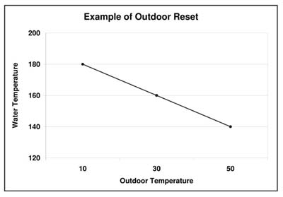
NOTE: C011 and C012 configurations must be set for the hottest temperature zone in the installation. C011 is the highest temperature the system will target and C012 is the lowest temperature the system will target during a heat call. Outdoor reset is done using these two temperatures. (See graph, temperatures in °F.)
|
 CAUTION CAUTION
Risk of high temperature water. Can cause property damage. Improper water temperature settings can result in damage to the floor covering. Make sure the maximum and minimum water temperatures are appropriate for the application.
|
C011 |
L000 |
Maximum Outlet Water Temperature |
140°F |
The value set indicates the maximum outlet water temperature to be targeted. The targeted outlet water temperature is affected by the values in C001 and C002. For example, if the value in C001 = 50°F; C002 = 10°F; C011 = 180°F; C012 = 140°F, then at an outdoor temperature of 30°F, the targeted outlet water temperature would be 160°F. |
C012 |
L001 |
Minimum Outlet Water Temperature |
140°F |
The value set indicates the minimum outlet water temperature to be targeted. The targeted outlet water temperature is affected by the values in C001 and C002. For example, if the value in C001 = 50°F; C002 = 10°F; C011 = 180°F; C012 = 140°F, then at an outdoor temperature of 30°F, the targeted outlet water temperature would be 160°F. |
C013-C021 |
L003, L062-L073 |
Time Clock Module Configuration |
C013:244, Rest:0:00 |
These configuration settings are used to configure the peak control times when utilizing the optional Steffes Time Clock Module. Refer to the installation and configuration instructions included with the module for more information. |