THIS PROCEDURE MUST BE PERFORMED BY A QUALIFIED TECHNICIAN.
To ensure safety, the 2100 Series room heaters are equipped with a core charging high limit switch and a clearance violation limit switch. These switches run along the back and the top front of the heater. If the exterior of the heater becomes too hot, the limit switch(es) will open and interrupt power to the heating elements. When one or both limits open, “Core Fail” will appear on the heater’s display panel.
Core Fail errors often have multiple causes. Evaluating system operation ensures that we quickly and successfully remedy the root cause(s) of the error. Following are instructions to assist in troubleshooting and repairing a system showing Core Fail.
Record Locations
Record the values in L130, L131, and L132 before powering off the heater.
Check room temperature.
If room temperature exceeds 85°F/29°C, the core charging high limit switch and/or the clearance violation high limit switch can trip prematurely. If the room temperature is above 85°F/29°C, determine the root cause of the overheating. For more information, reference the Heater Over/Under Charges Flow Chart.
Check clearances.
Violating clearances can affect airflow around the heating system. If airflow is blocked, the core charging high limit switch and/or the clearance violation limit switch can trip due to overheating. Verify nothing has fallen behind the heater, nothing has been draped over the top or front of the heater, and no furniture or home décor has been placed within the required clearance areas.
Check the outdoor temperature sensor for proper operation if using automatic charge control.
Use the HELP Menu to determine if the outdoor temperature reading is correct. If the outdoor temperature is lower than actual outdoor temperature, the heater may overcharge.
Verify the following programming information for charging.
- L010/C000 = 5
- L012/C001 = temperature the heater will start charging
- L013/C002 = temperature the heater will try to achieve a full charge
- L010/C000 = 6
- Verify the desired core charge level is not set too high for the current heating requirements of the area by pressing and releasing the M button until “Core” is displayed.
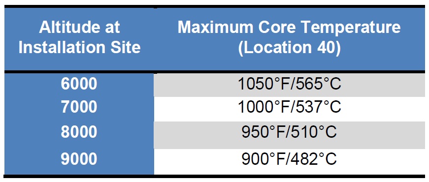
Check the Maximum Core Temperature as set in Location 40 (L040).
The value in L040 is set to a factory default of 1100°F/593°C. If the value in L040 exceeds 1100°F/593°C, the heater can overheat and cause one or both high limit switches to fail. If the heater is installed at an elevation over 6,000 feet, the value in L040 needs to be adjusted accordingly.
Verify the core charging and clearance violation high limit switches are closed.
All 2100 Series heaters have a core charging high limit switch. Heaters built after May 31, 2012 also include a clearance violation high limit switch. The wiring from these limits should be connected to the “Limit 1” and “Limit 2” terminals on the base I/O relay board. If the heater has a clearance violation limit, the limits should be connected in series with each other. These limits will open on temperature rise. If the heater is cold to the touch and one or both limits are open (have not reset), replace the limit switch(es). If a manual reset limit switch will not reset and the limit is open, replace the limit switch.
Check heating elements and heating element relays.
Place the heater into a charge mode and use the Charge Control Override, to have the heater target 100% core charge. Use the HELP Menu to verify the heating elements active (HE) is 4. Check amp draw to verify all 4 elements are energized. For more information, reference the Heater Does Not Charge Flowchart.
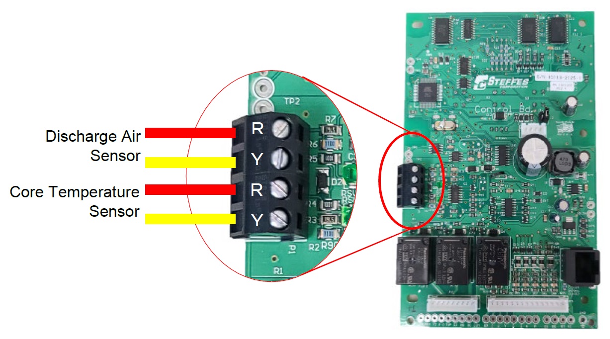
Verify wiring of core temperature sensor.
- Core temperature sensor must be connected to the bottom two positions on the 4-position terminal block on the processor control board.
- Core temperature sensor is polarity sensitive. Verify the red wire is on top (R) and the yellow wire is on bottom (Y).
- Verify connections are tight.
- Verify none of the insulation fibers are under the terminal screw.

Verify the Current Core Temperature reading in Location 110 (L110).
Use the K-Type Thermocouple Output Chart to compare the core temperature sensor mVDC reading to the processor control board temperature. The current core temperature reading for the 2100 Series heaters is Location 110 (L110).
Check calibration of the processor control board.
Install a copper jumper in place of the core temperature sensor on the lower two positions on the 4-position terminal block on the processor control board. L110 should read approximately 60-90°F/15-32°C. This temperature reading will vary based on ambient room temperature.
Test the core temperature sensor.
Read mVDC across the core temperature sensor wires with them connected to the bottom two positions on the 4-position terminal block on the processor control board. Then disconnect the core temperature sensor and read mVDC across the wires. Compare the two readings. They should be within 0.5 mVDC of each other. If not, replace the core temperature sensor.