Part 54 Description - 5100 Series
Heat Exchanger Assembly
The exchanger is located in the base of the system. The primary loop gets plumbed directly to the inlet water port of the exchanger. The pressure relief valve is plumbed to the outlet water port and then the primary loop piping is connected to the pressure relief port.
When a heat call is received from one or more of the zones in the application, the primary loop pump (circulator) is energized and water begins to flow through the exchanger. The output water sensor senses the temperature of the water and sends this information to the processor control board. The processor control board then sends information to the base I/O relay board to power the core blower. The core blower extracts heat from the core. This heat passes over the exchanger, heating the water as it flows through. The discharge water temperature is determined by the values in Location 0 (L000) and Location 1 (L001).
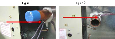
For heaters with serial numbers before 210085219014962SHH the supply water sensor tube will be located on the bottom of the outlet pipe (Figure 1 below), after that the outlet water sensor tube will be located on the side of the outlet pipe (Figure 2 below).
Exchanger capacity = 1.2 gallons, see link below.