THIS PROCEDURE MUST BE PERFORMED BY A QUALIFIED TECHNICIAN.
The heat exchanger kit (Item # 1100100R) is to replace a damaged or defective heat exchanger in the 5100 Series Comfort Plus Hydronic heating systems. Each heat exchanger kit includes a heat exchanger, ½” insulation blanket, screws, high temperature red silicone, the exchanger left side inner panel, the exchanger left side outer panel, two exchanger access tube covers, and the painted exchanger left side access panel.
WARNING

HAZARDOUS VOLTAGE: Risk of electric shock. Can cause injury or death. System may be connected to more than one branch circuit. Disconnect power to all circuits before installing or servicing. Equipment must be installed and serviced by a qualified technician.
HIGH TEMPERATURES: Risk of personal injury. DO NOT install Heat Exchanger when outer surfaces of the Comfort Plus Hydronic system are hot, and if the old exchanger is still hot.
INSTALLATION
Power Down System
De-energize the heating system.
Remove Left Side Access Panel
Remove the exchanger left side access panel (Figure 1A) covering the heat exchanger and discard.

Detach Plumbing
Detach any plumbing.
Disconnect Wires from Limit Switches
Cut the tie wraps connecting the wires, and disconnect the wires from the limit switches. Remove the outlet water temperature sensor wire from the heat exchanger outlet pipe.
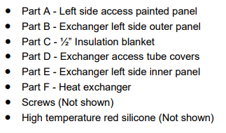
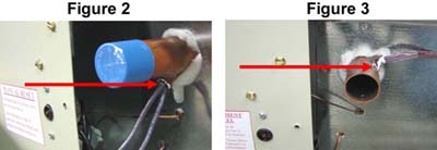
NOTE: For heaters with serial numbers before 210085219014962SHH the supply water sensor tube will be located on the bottom of the outlet pipe (Figure 2). For heaters after 210085219014962SHH the outlet water sensor tube will be located on the side of the outlet pipe (Figure 3).
Remove Limit Switches
Unscrew the two limit switches from the base back left side painted panel. Remove both the upper and lower limit switches from the heat exchanger. Set the limit switches off to the side so that they will not get damaged or forgotten.
Remove Outer Left Side Panel
Remove the outer left side exchanger panel (Figure 1B) and discard.
Remove Insulation Blanket
Remove the ½” insulation blanket (Figure 1C) and discard.
Remove Access Tube Covers
Remove the exchanger access tube covers (Figure 1D). You may want to use a flat screwdriver to pry the covers off of the silicone. Discard the old tube covers.
NOTE: The outlet tube cover is in two (2) pieces.
Remove Inner Left Side Panel
Remove the inner left side exchanger panel (Figure 1E) and discard.
Remove Old Exchanger
Remove the old heat exchanger.
Prepare New Exchanger
Remove new heat exchanger from the shipping box and inspect the exchanger for physical damage. If the fins are bent, use a fin comb to comb them out.
NOTE: If the exchanger has plastic caps on the tubes, keep them on, so that no foreign materials get into the tubes while doing the installation.
Slide New Exchanger into System
Slide the heat exchanger into the base of the furnace.
NOTE: There may be slight dimensional differences between the original heat exchanger and the new heat exchanger.
Position Exchanger
Insert the exchanger until the rear flanges of the exchanger are up against the right side exchanger panel. With the exchanger pressed against the right side exchanger panel, slide the exchanger so that it is flush against the rear of the base assembly (Figure 4).
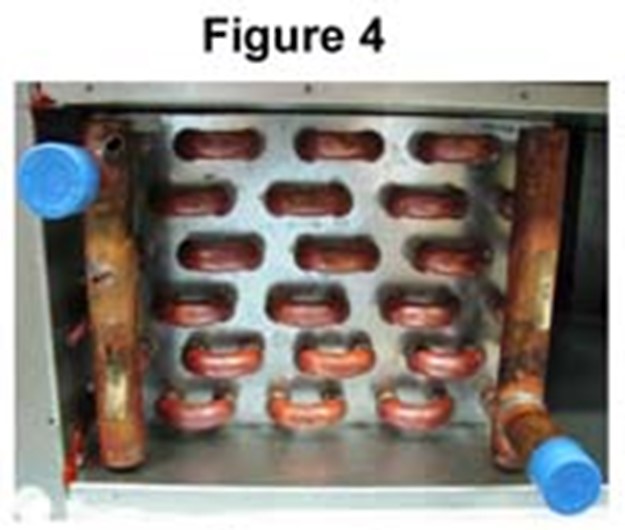
NOTE: The outlet tube must be in the top left corner when installing the heat exchanger into the base of the furnace, as shown in figure 4.
Verify the Cover Fits Correctly
Verify that the cover will fit around the supply water sensor tube, limit tubes, and into the opening of the heat exchanger compartment on the base of the heater (Figure 5).
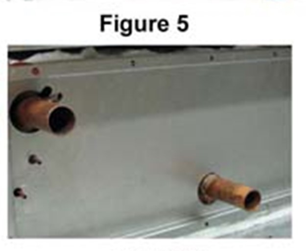
Place New Left Inner Panel
Place the new left side inner panel onto the inlet and outlet pipe of the heat exchanger to ensure proper fit. Make any adjustments needed to have proper installation of the heat exchanger. If there is adequate clearance, remove panel and apply the high-temperature red silicone (provided) to the inside bends of the exchanger left side inner panel and put back in place. A light tapping with a hammer may be required to properly seat the panel in the opening (Figure 5).
NOTE: Do not screw the exchanger left side inner panel on yet.
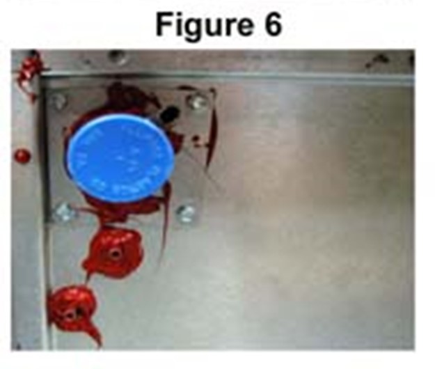
Secure Cut Access Tube Covers
Apply the high-temperature red silicone to the exchanger access tube covers. Place half of the cut tube cover on the side of the outlet pipe of the heat exchanger. Place the other half of the cut tube cover on the other side of the outlet pipe of the heat exchanger. Secure the two (2) exchanger access tube cover halves to the exchanger left side inner panel with four (4) self drilling screws included (Figure 6).
Secure Uncut Access Tube Cover
Slide the uncut access tube cover over the inlet pipe of the heat exchanger. Secure the access tube cover to the exchanger left side inner panel with four (4) self drilling screws included (Figure 7).
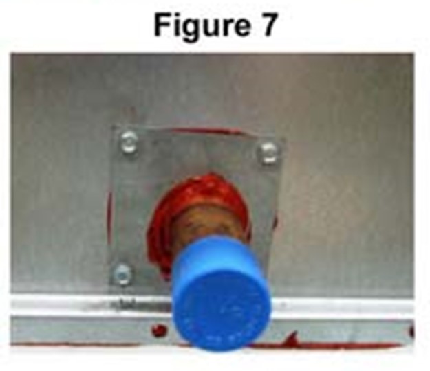
Apply High Temperature Silicone
Apply high temperature red silicone around all the open areas of the exchanger access tube covers and sensing wells as shown in Figures 6 and 7.
NOTE: Use caution while applying silicone to keep the silicone out of the heat exchanger limit tubes and sensing wells.
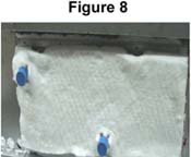
Install Insulation Blanket
Hold the piece of 1/2" insulation blanket up against the heat exchanger pipes in the position the insulation will be in when installed into the exchanger left side inner panel. Use a knife to make “X” cuts into the insulation at the points the exchanger pipes will go through. Press the 1/2" insulation blanket into the pocket of the exchanger left side inner panel. The limit tubes will poke through the insulation as the insulation gets closer to seating in the panel (Figure 8).
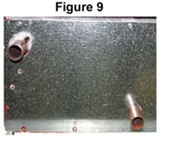
Place Outer Left Side Panel
Place the outer left side panel (Figure 1B) onto the inlet and outlet pipes of the heat exchanger (Figure 9).
Secure Inner and Outer Exchanger Panels
Secure the inner and outer left side exchanger panels to the heating base assembly with the 5/8” screws provided.
Remove Plastic Caps
After the outer left side exchanger panel is fastened to the base of the furnace, remove the plastic caps if still on, and insure that the ends of the limit tubes are not plugged with insulation.
NOTE: DO NOT use water-based lubricant to aid in the installation of the high limit switches.
NOTE: The straighter the limit capillary, the easier it will be to install.
Insert Lower Limit Switch
Insert the lower, 225°F auto reset limit switch (the one with the galvanized mounting spoon attached) into the lower left limit tube of the heat exchanger (Figure 10).

Insert Upper Limit Switch
Insert the upper, 250°F manual reset limit switch (the one with the stand-offs attached) into the top right limit tube of the heat exchanger (Figure 10).
NOTE: The limit capillaries should slide into the limit tubes of the heat exchanger until there is approximately 6” – 7” remaining out of the limit tube (Figure 10).
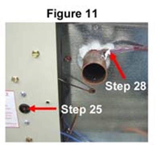
Reattach Limit Switches
Reattach both limit switches to the base back left side painted panel. Be sure to install the manual reset in the cut out hole in the painted panel as shown in Figure 11.
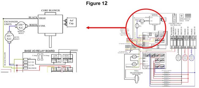
Reconnect all Wiring
Reconnect all of the wires that where disconnected, be sure to connect them to the proper limit switches. Reference the line voltage wiring diagram for more information (Figure 12).
Reconnect Plumbing
Reconnect all of the plumbing to the heat exchanger.
Reinstall Outlet Water Temperature Sensor
Reinstall the outlet water temperature sensor (Figure 11).
NOTE: To avoid possible wire damage, ensure the wires do not bend sharply where they enter the sensing well.
Install New Painted Left Side Panel
Install the new painted left side exchanger access panel.