THIS PROCEDURE MUST BE PERFORMED BY A QUALIFIED TECHNICIAN.
 WARNING
HAZARDOUS VOLTAGE: Risk of electric shock. Can cause injury or death. Heater may be connected to more than one branch circuit. Disconnect power to all circuits before servicing.
Power Off and Remove Front Panel
Disconnect power to all branch circuits of the heater and remove the painted front panel.
Hinge the Right Side Panel
Hinge the right side panel open by A) removing the screw located above the grill slats on the lower right side of the heater; B) loosening the screw located at the top right corner of the electrical compartment; and C) pushing out on the right side panel. Refer to Figure 1.
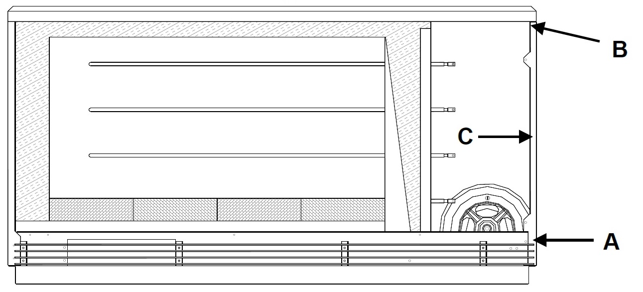

Figure 1
Unplug Cable
Disconnect the interface cable from the processor control board
Disconnect Orange Wires
Disconnect the two (2) orange wires from the damper actuator assembly to the base I/O relay board. One wire is connected to the damper terminal and one wire is connected to an orange jumper wire (L2).
Remove Actuator
Remove the damper actuator assembly by removing the screws holding it in place.
Inspect New Part
Inspect the two (2) resistors on the new actuator assembly. Verify there are no cracks, chips, or other physical damage.
Verify Resistor Placement
Verify the resistors are aligned and secured on the actuator as shown in Figure 2.
NOTE: The resistors must be secured to the actuator or the actuator assembly will not operate properly.
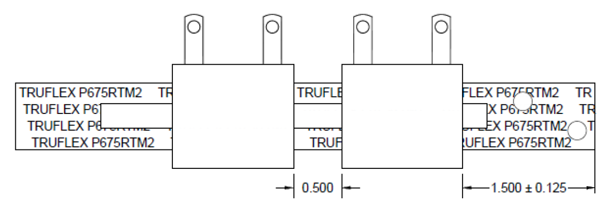
Figure 2
Measure Resistance
Measure the ohm value across the orange wires on the damper actuator assembly.
-
120V = 256 - 284 ohms
-
240/208V = 1026 - 1134 ohms
Install Actuator
Install the new damper actuator assembly so the bimetal strip is above the damper rod (Figure 3).
NOTE: Writing on the bimetal strip MUST face downward.
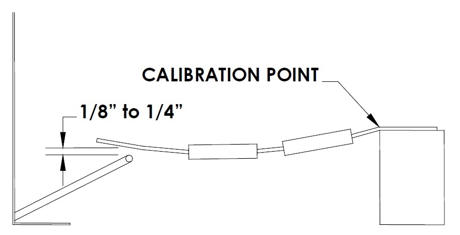
Figure 3: 2100 Series (Front View)
Check Clearance
Verify the gap between the bimetal strip and the damper rod. At room temperature, it should be approximately 1/8” – 1/4”. Calibrate, if necessary, by bending the actuator near its mounting point as shown in Figure 3.
NOTE: Do not change the radius of the bimetal strip in the resistor region.
Figure 3: 2100 Series (Front View)
Connect Wires
Route the orange wires from the damper actuator assembly to the base I/O relay board and connect one wire to the damper terminal and one wire to the orange jumper wire from L2.
Check Wiring
Verify the heater wiring does not interfere with the operation of the damper actuator assembly.
Verify Operation
Verify damper operation to ensure optimum performance of the heater. Verify the damper opens and closes freely by pressing down on the damper rod. Slowly release pressure on the damper rod to verify the damper does not stick when closing.
Reassemble Heater
Reassemble the heater and restore power.
Perform Checkout Procedure
Complete the Air Discharge System Check Out procedure.