THIS PROCEDURE MUST BE PERFORMED BY A QUALIFIED TECHNICIAN.
 WARNING
HAZARDOUS VOLTAGE: Risk of electric shock. Can cause injury, or death. System may be connected to more than one branch circuit. Disconnect power to all circuits before servicing.
Power Off Unit
Disconnect power to all branch circuits of the heater and remove the painted front panel.
Hinge the Right Side Panel
Remove Grill Slats
Remove and set aside the grill slats. Check the blower wheel for dirt and/or debris and clean if necessary.
Check Output Sensor Clearance
Check the clearance between the output sensor and the discharge air high limit switch. The tip of the output sensor should be located within 1/4” - 1/2” from the face of the discharge air high limit switch (Figure 2).
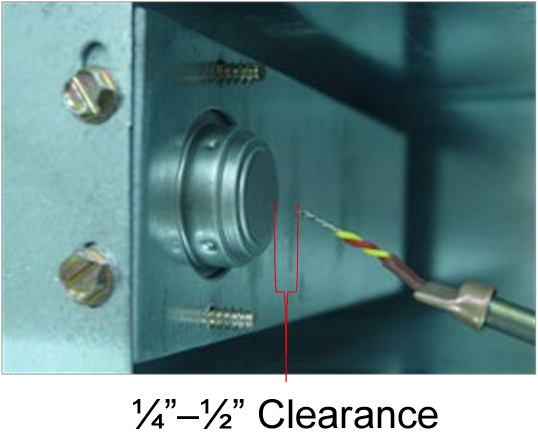
Figure 2 - Auto Reset
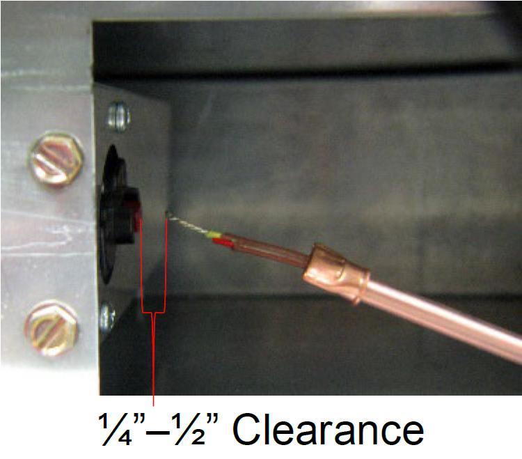
Figure 2 - Manual Reset
Check Damper Clearance
Check the clearance between the damper actuator and the damper lever (Figure 3). The damper actuator should be above the lever. With no heat call, the resistors on the damper actuator assembly should be cool and the clearance between the actuator and the lever should be between an 1/8 - 1/4". If necessary, calibrate by bending the actuator near its mounting point (Figure 3).
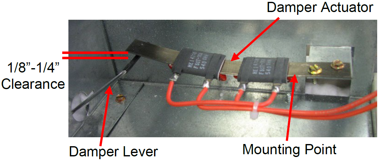
Figure 3
Check Resistor Spacing
Verify spacing of resistors on damper actuator as shown in Figure 4.
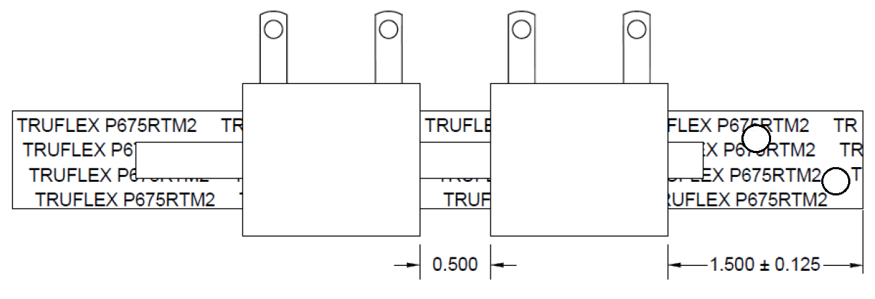
Figure 4
Check Damper Movement
Check damper operation by manually pressing the damper lever down and then slowly raising it. If the damper is not free, remove the blower and clean any debris in that area.
Check Actuator Resistance
Disconnect the orange wire from the "damper" terminal on the base I/O relay board
-
240V or 208V HEATERS: Read resistance between the orange wire and the terminal labeled "L2 240". Resistance value should be approximately 1080 ohms. If incorrect, replace the damper actuator assembly.
-
120V HEATERS: Read resistance between the wire and the terminal labeled "L2 120". Resistance value should be approximately 270 ohms. If incorrect, replace the damper actuator assembly.
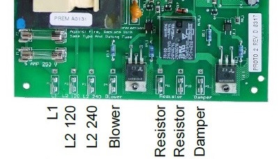
Figure 6
Connect Orange Wire
Reconnect the orange wire.
Verify Blower Resistor
Verify that the blower resistor is the correct value for the application:
|
BLOWER RESISTOR OHM VALUE (All resistors are 50 Watt +/- 10%) |
||
|---|---|---|
|
Blower Mfg |
Input Voltage |
Blower Speed Resistor Required |
|
FASCO |
120V |
150 Ohm 50W |
|
FASCO |
208/240V |
600 Ohm 50W |
|
P-Tech/Jakel |
120V |
250 Ohm 50W |
|
P-Tech/Jakel |
240V |
1100 or 1500 Ohm 50W |
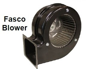
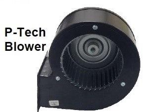
Figure 5 - Fasco
Test Blower Resistor
Disconnect a lead from one (1) of the two (2) "resistor" terminals on the base I/O relay board. Measure resistance between the removed wire and the other "resistor" terminal. If incorrect, replace the blower resistor.
Reconnect blower resistor wire and energize the heater. Set the room temperature set point four (4) degrees lower than the current room temperature. The blower should NOT be operating.
Verify Operation
Description of Operation
The processor control board receives a heat call when the room temperature set point is higher than the current room temperature. When a heat call is received, the processor control board tells the base I/O board to energize the blower and the damper. Location 120 and 121 (L120 and L121) indicate what speed the processor control board wants the blower and damper to operate at.
The values in L120 and L121 are then used to determine how much voltage the base I/O board should send to the blower (L2 240 to Blower) and the damper (L2 240 to Damper). Reference Base IO image. Using the values from L120 and/or L121 and the Blower Activation chart, determine what the voltage reading from L2 240 to Blower and/or L2 240 to Damper should be. Then check voltage across those terminals to verify proper operation.
NOTE: If testing a heater with a 120V control circuit, use L2 120 terminal instead of L2 240 for testing voltage going to the blower and the damper.
2100 Series heaters have a variable speed blower and damper that are regulated by varying voltage to the corresponding terminals through triacs on the base I/O relay board.
The blower and the damper actuator should respond to the voltage being sent from the base I/O board. With a heat call, L120 and L121 should have values greater than zero and there should be voltage across the L2 240 and blower/damper terminals. The blower should be running, and the damper actuator should be opening the damper. Without a heat call, the values in L120 and L121 should be zero and there should be no voltage across L2 240 and the blower/damper terminals.
NOTE: The following instructions make sure the processor control board, base I/O board, blower, and damper respond appropriately for the heat call status of the heater. If any of the readings are incorrect, reference the associated flow charts (several listed at the bottom) or contact Steffes Technical Support.
Connect Blower Wire
Reconnect blower resistor wire and energize the heater.
Verify Operation Without a Heat Call
Set the room temperature set point four (4) degrees lower than the current room temperature.
Verify Operation With a Heat Call
Set the room temperature set point one (1) degree above actual room temperature.
- L120>0
- L121>0
- Use L120 and this chart to determine what voltage from L2 240 or L2 120 to Blower should be. Check voltage.
- Use L121 and this chart to determine what voltage from L2 240 or L2 120 to Damper should be. Check voltage.
- Blower should be operating.
- Damper should be opening.
Reassemble
Reassemble the heater.