NOTE: The damper assembly is NOT field replaceable. Contact Steffes for more information.
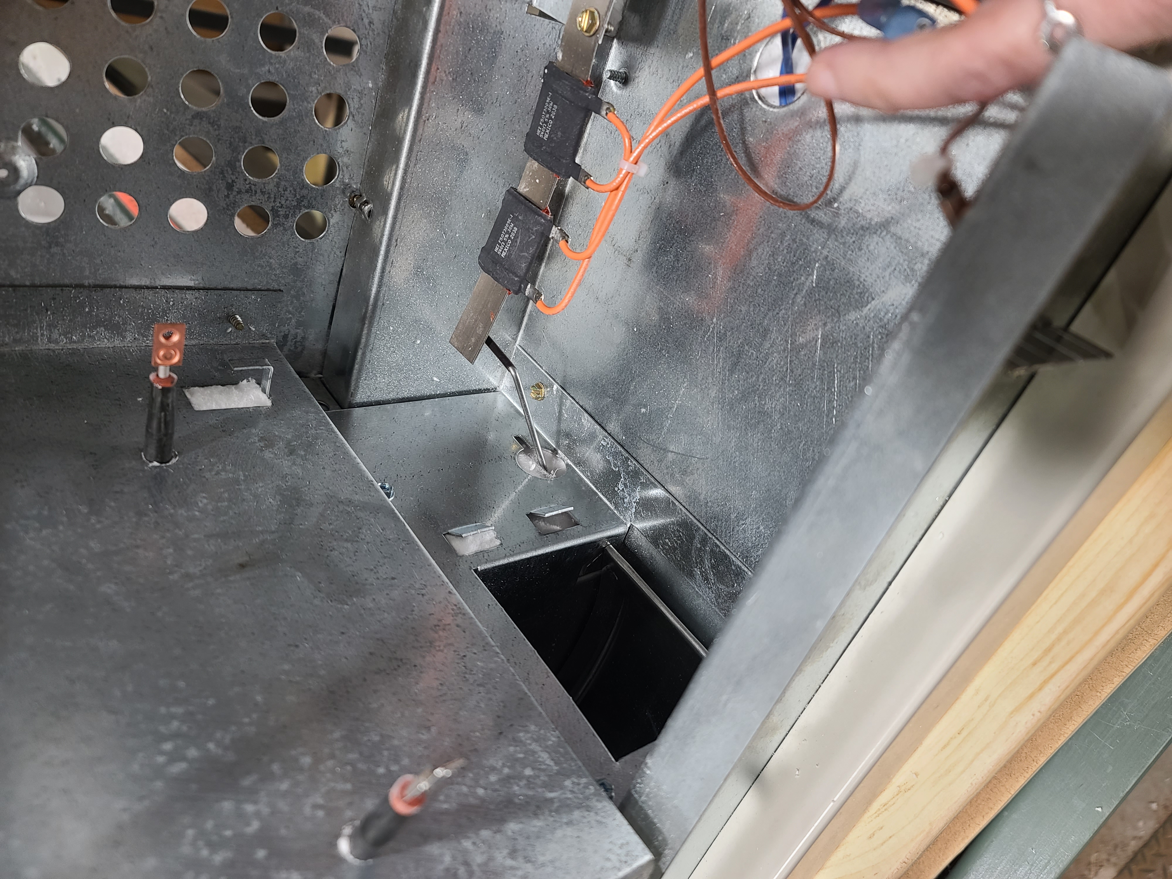
The damper assembly is used to regulate the amount of air flow through the brick core. When a heat call is active, voltage is applied to the damper actuator resistors. As the resistors heat up, the bimetal actuator bends down and pushes on the damper rod, raising the damper.
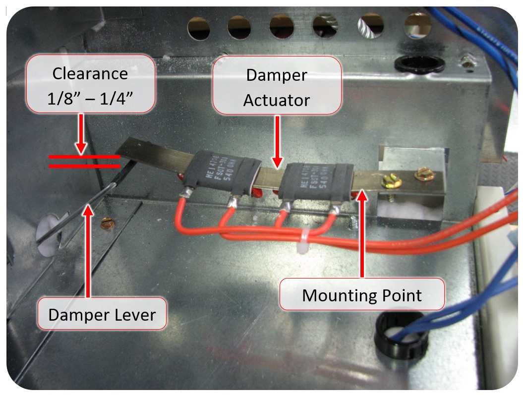
During brick installation, brick debris can fall down into the damper and cause it to catch. Therefore, it is important to verify that the damper operates properly during the final system check-out. To test the damper, push down slowly on the damper lever until it stops. When pushed down, there should be about 1/8" clearance between the damper lever and the base of the heater. Slowly release the damper lever and let the damper return to its resting position. The damper lever should be approximately 1/8 - 1/4" below the damper actuator when the resistors are cool and the damper is at rest. There must be 1/32" of free play front to back when pushing and pulling the damper lever.
If problems with the discharge air system of the heater occur, complete the discharge air check-out procedure.