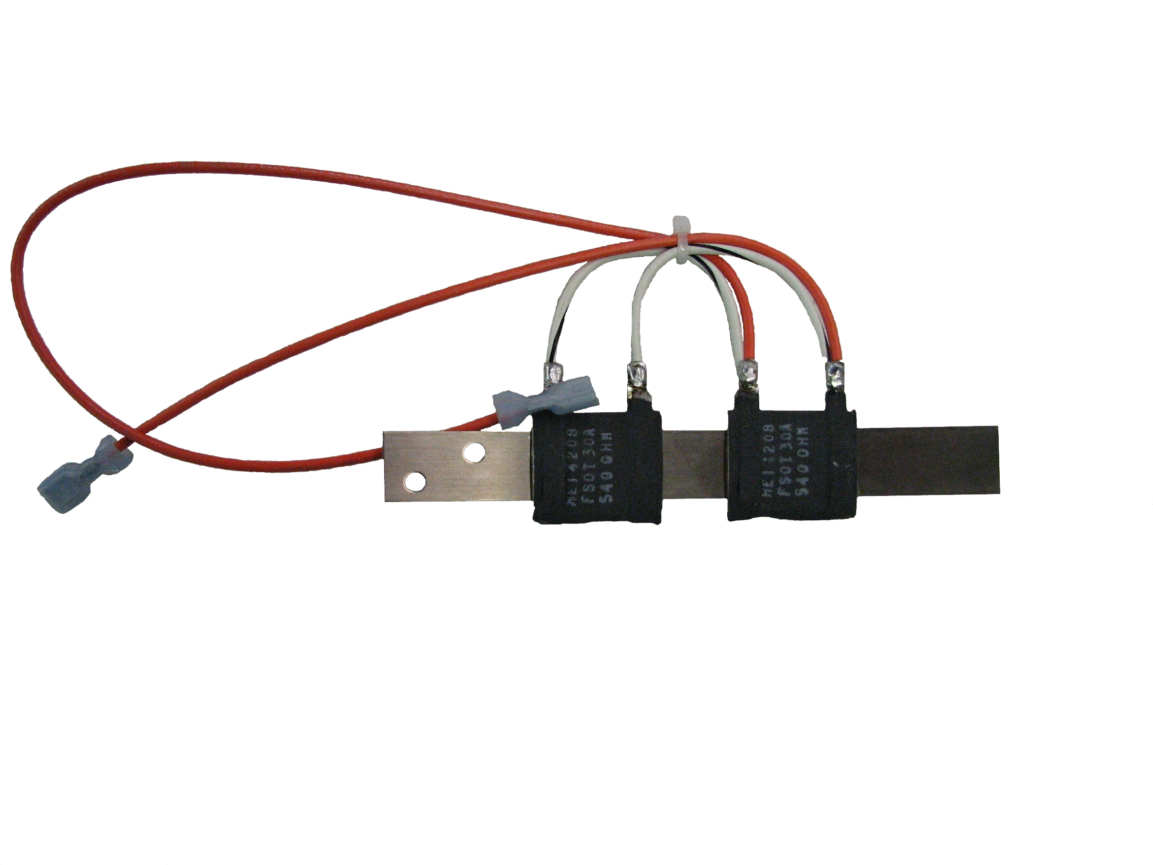
120V Damper Actuator
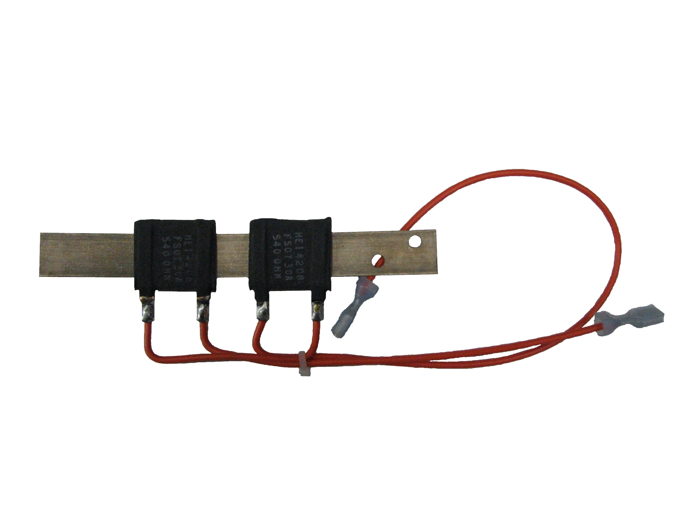
240V Damper Actuator
During a heat call, voltage is applied to the resistors on the damper actuator assembly. As the resistors heat, the bimetal bends and "actuates" the damper so heat can be extracted from the brick core. Voltage from the base I/O relay board is varied to regulate the discharge air temperature. As the voltage to the damper actuator assembly is increased, the temperature of the resistors on the actuator rises causing the actuator to move down and open the damper more. This allows more air flow through the core and increases the discharge air temperature.
In resting position, the clearance between the damper actuator and the damper lever should be approximately 1/8 - 1/4". To verify correct resistance of the actuator, disconnect the orange wires from the base I/O relay board and take an ohm reading across the wires. The resistance value should be approximately 1080 ohms on a 240 volt system and about 270 ohms on a 120 volt system (+/- 10%). Placement of the resistors on the actuator strip is important. Refer to the Damper Actuator Replacement Procedure to verify proper alignment.
120V Damper Actuator
240V Damper Actuator