THIS PROCEDURE MUST BE PERFORMED BY A QUALIFIED TECHNICIAN.
If you have not done so already, please review the generic installation steps here.
THIS PROCEDURE MUST BE PERFORMED BY A QUALIFIED TECHNICIAN.
If you have not done so already, please review the generic installation steps here.
NOTE: One sensor per heater is required when connecting an outdoor sensor directly to the heater.
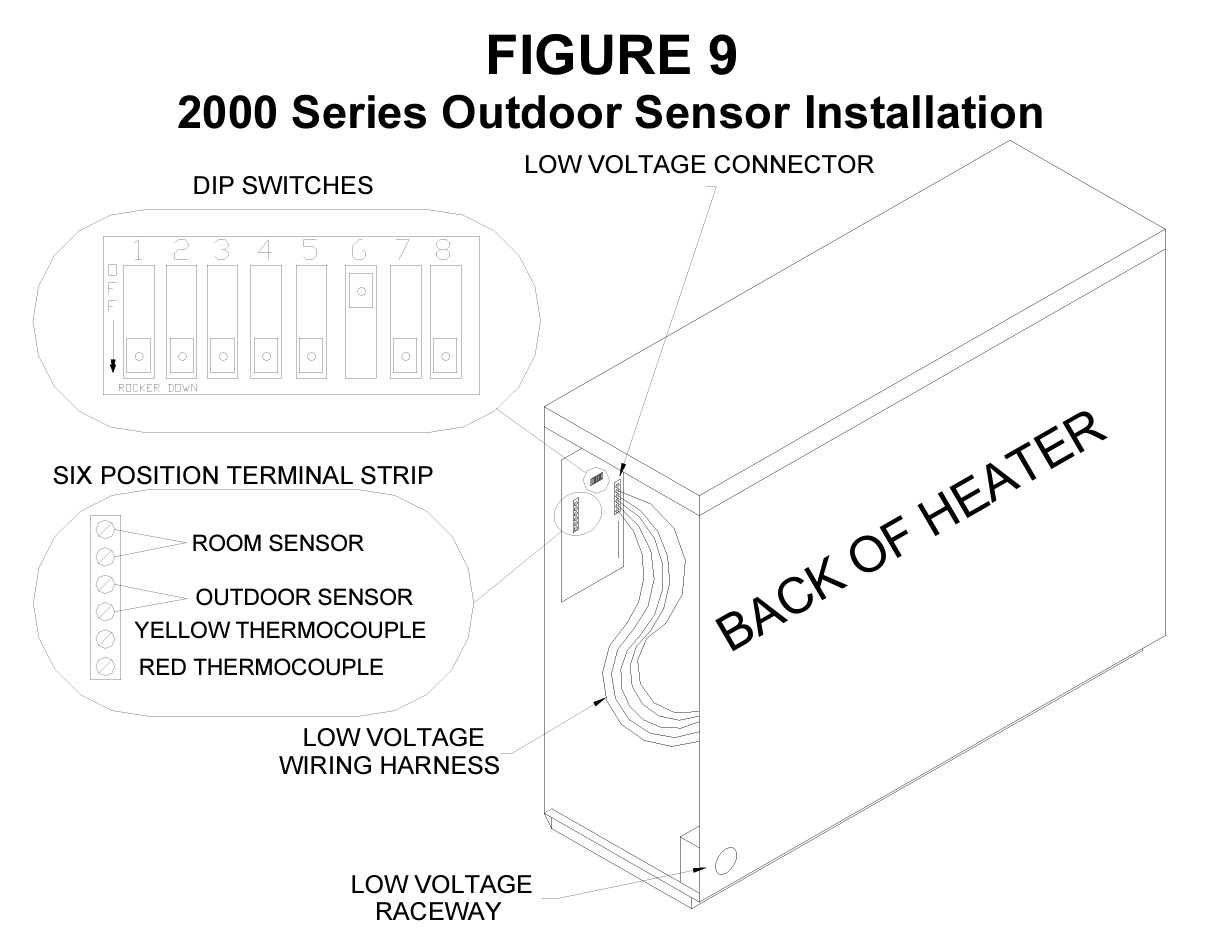
Disconnect power to the heater and remove the painted front panel. Slide the control board mounting plate off the mounting screws and place it in the service position.
In the low voltage raceway at the back of the heater, connect the wire routed from the outdoor sensor to two unused wires from the heater's low voltage wiring harness.
NOTE: Generally, the blue/yellow and the orange/black wires can be used to connect the outdoor sensor.
Trace the two wires connected to the outdoor sensor wires from the low voltage harness up to the low voltage connector (Figure 9) on the control board. At the connector, cut and strip the wires.
Connect these wires to the two "OS" positions of the six-position terminal strip (Figure 9).
Place DIP switch #6 in the "ON" position.
Reassemble the heater and restore power.
Verify programming is correct and proper outdoor temperature is being received using Location L46.
NOTE: The right green indicator light on the control panel should illuminate, indicating automatic charge control is being utilized.
1200119 Rev 12 6/14/2022