THIS PROCEDURE MUST BE PERFORMED BY A QUALIFIED TECHNICIAN.
 WARNING
HAZARDOUS VOLTAGE: Risk of electric shock. Can cause injury or death. Heater may be connected to more than one branch circuit. Disconnect power to all circuits before servicing.
Note:
If not already completed, please review the Operation Section. It contains important notes that should be read before proceeding.
Applicable Heaters
This section of the procedure is applicable to current production heaters (beginning January 2019) that have White and White/Black wires in the Low Voltage Harness.
If the unit does not have these wires, use this procedure.
To configure the heater to operate with a low voltage thermostat perform the following:
Mount Thermostat
Mount the thermostat in the desired location and connect wiring in the manner which is appropriate for the application according to Figures 1 and 2.
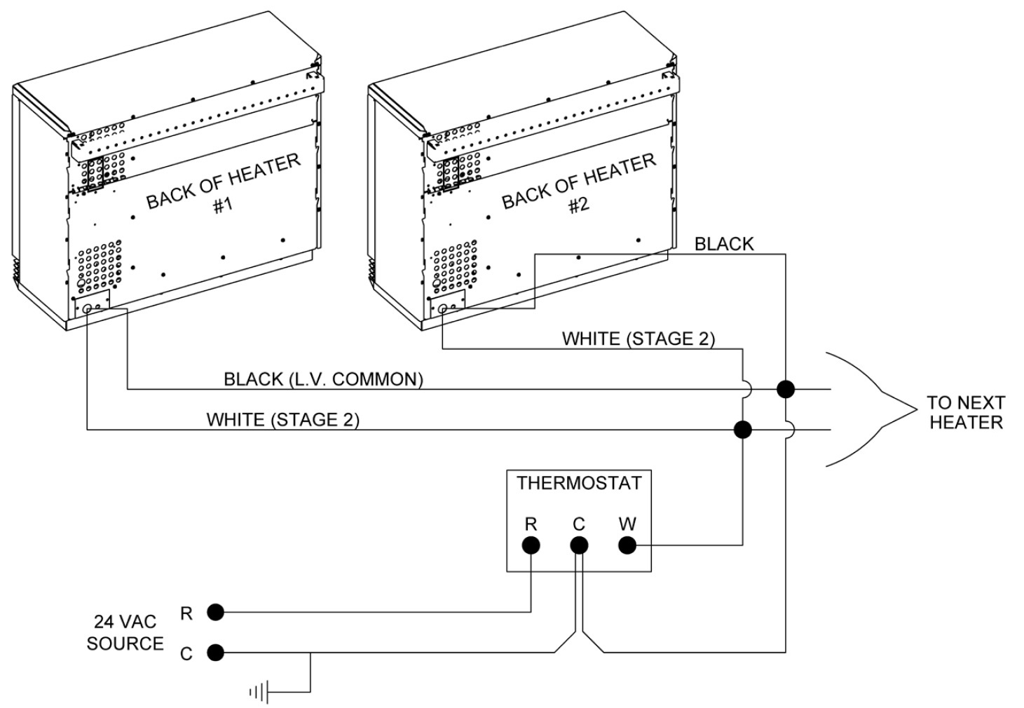
Single Stage Wiring (Figure 1)
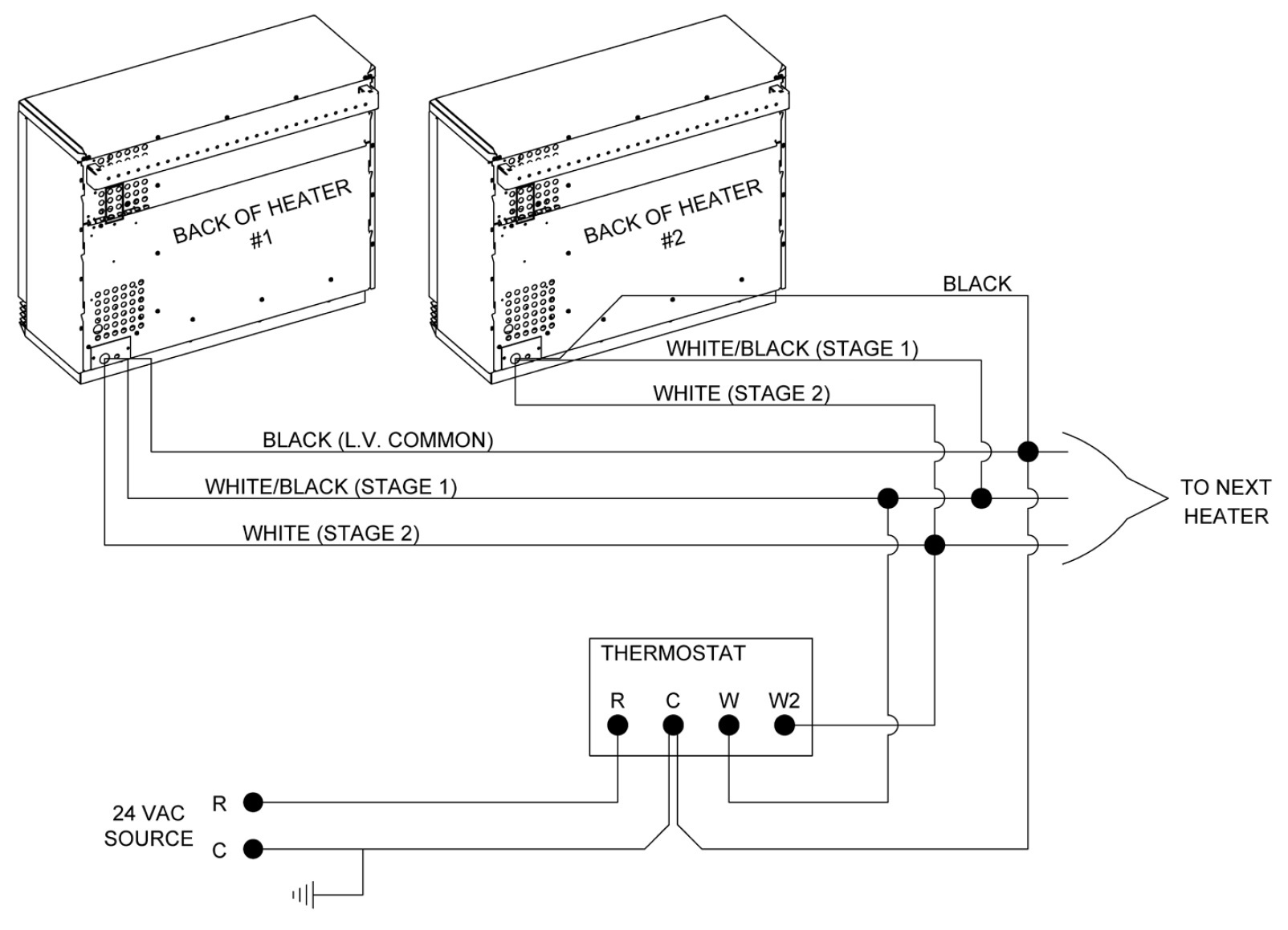
2 Stage Wiring (Figure 2)
Configure Wiring/L035
Version 2.02 or Lower Only: Disconnect one of the wires from the fan resistor on each heater.
Version 2.04 or Higher Only: Remove the 2-bit from the value in Location 35 (L035). Unless other changes to the heater’s configuration have been made, the new value will be 152.
Set L003
Set the value in Location 3 (L003) to a value of 32 to display heat call status or a value of 16 to display outdoor temperature.
Adjust Blower Speed and Temperature
Set the values in Location 28 (L028), 29 (L029), 48 (L048), and 49 (L049) as shown in Table 1.
Table 1
| Model | |||||
|---|---|---|---|---|---|
| Location | 2102 | 2103 | 2104 | 2105 | 2106 |
| L028 | 1 | ||||
| L029 | 10 | 33 | 55 | 78 | 100 |
| L048 | 90 | ||||
| L049 | 200 | ||||
| Model | |||||
|---|---|---|---|---|---|
| Location | 2102 | 2103 | 2104 | 2105 | 2106 |
| L028 | 5 | ||||
| L029 | 20 | 65 | 110 | 155 | 200 |
| L048 | 180 | ||||
| L049 | 200 | ||||