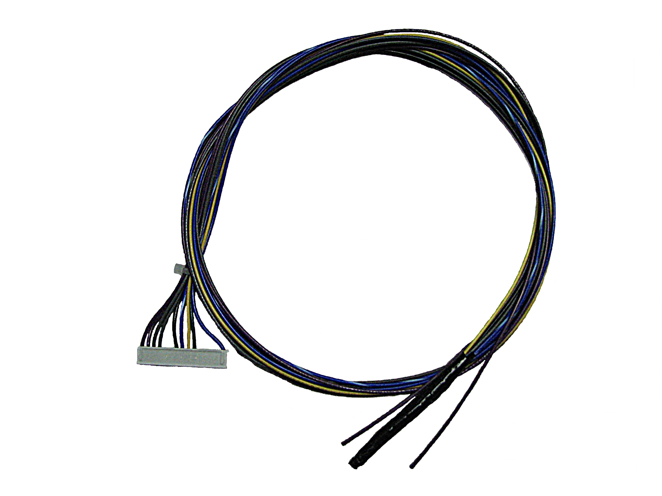
The low voltage wiring harness is connected to the processor control board and routes through the electrical compartment to the low voltage raceway. It contains the wires which connect to the room temperature sensor, a direct wired outdoor temperature sensor, low voltage thermostat, low voltage setback signal, and/or the peak control device when utilizing low voltage direct wired peak control. The harness changed Jan 1st, 2019 when white and white/black wires were added to simplify low voltage thermostat wiring. Refer to the Internal Low voltage Wiring Diagram for specifics.
The heater’s supply power (blue wire) will generally be adequate to connect multiple heaters. However, depending on length of wire and number of heaters installed, an external power supply may be required. This blue wire is 20VDC nominal and has limited current output through a 600ohm resistor so that a short to ground will not damage the circuit board (15.8mA max).
NOTE: DO NOT route low voltage wires in close proximity to line voltage wiring as induced voltage across the wires will cause inaccurate temperature reading and may cause damage to the processor control board.