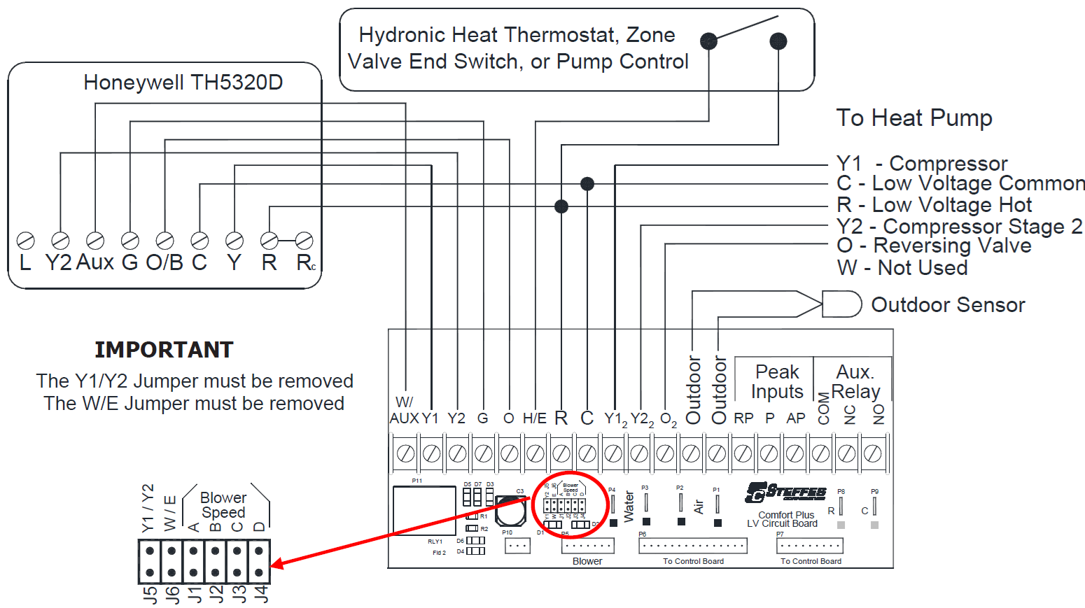
Two Stage Heat Pump Application
|
Two Stage Heat Pump with Auxiliary Heat / Two Stage Cool *** |
||||||
|---|---|---|---|---|---|---|
|
Thermostat Stage |
Thermostat Output |
Heat Pump Stage |
Low Voltage Circuit Board Output to Heat Pump* |
% of Selected CFM |
Heat Call Status on Digital Display* |
Discharge Air Temperature Target |
|
1 |
Y/G |
1 |
R/Y12 |
50% or 70%** |
HC_1 |
|
|
2 |
Y/Y2/G |
2 |
R/Y12/Y22 |
100% |
HC_1 |
|
|
3 |
Aux/Y/Y2/G |
2 |
R/Y12/Y22 |
100% |
HC_2 |
|
|
Fan |
G |
0 |
R |
400 CFM |
HC_F |
N/A |
|
Cool 1 |
Y/G/O |
1 |
R/Y12/O2 |
50% or 70%** |
COOL |
N/A |
|
Cool 2 |
Y/Y2/G/O |
2 |
R/Y12/Y22/O2 |
100% |
COOL |
N/A |
|
Hydronic |
Varies |
N/A |
N/A |
OFF |
HC3 |
N/A |
* If multiple inputs are active, system will display highest Heat Call values. "COOL" overrides all inputs and stops all heating operations.
** Systems built before 1/1/2011 are configured for 50% airflow in Stage 1. For more information, refer to this topic.
*** Thermostat must be programmed to energize the reversing valve for cooling. If outdoor unit used requires the reversing valve be energized for heating, see configuration menu C006