THIS PROCEDURE MUST BE PERFORMED BY A QUALIFIED TECHNICIAN.
For use with Variable Speed (ECM)
 WARNING
HAZARDOUS VOLTAGE: Risk of electric shock. Can cause injury, or death. System may be connected to more than one branch circuit. Disconnect power to all circuits before servicing.
Description
When a Steffes furnace configured with a variable speed (ECM) blower is interfaced to a 2-stage heat pump, the ECM motor will operate at 50% or 70% of the selected airflow in a low speed (stage 1) compressor mode depending on when it was manufactured. Reference the chart below for the % of airflow delivered based on the manufacturer's UL Identification Label. If installing a system which requires a change to the standard operation, a high speed stage 1 relay must be installed. Steffes recommends the Allen Bradley Relay #700-HA32A24 with Relay Base #700-HN125 or equivalent.
|
Manufactured for 50% Airflow V001 and V002 |
Manufactured for 70% Airflow V003 and above |
|
|---|---|---|
|
3100 Series Furnace |
206093221015357 VHH - 20111xxxxxxxxxx VHH |
After # 20111xxxxxxxxxx VHH |
|
4100 Series Supply Air Plenum |
506095A00023936 VHN - 50111xxxxxxxxxx VHN |
After # 50111xxxxxxxxxx VHN |
|
5100 Series Air Handler |
50709AH00023951 VHN - 50111xxxxxxxxxx VHN |
After # 50111xxxxxxxxxx VHN |
-
NOTE: The last six digits of the serial number are the unique number given to each heating system. If the last six digits are greater than the numbers above, that system can utilize this relay to enable this feature.
-
NOTE: If the UL Identification label has an option code of "003"; that system was built with a variable speed blower motor programmed for 70%.
INSTALLATION AND WIRING
De-energize the System
De-energize the Comfort Plus system and remove the electrical panel cover.
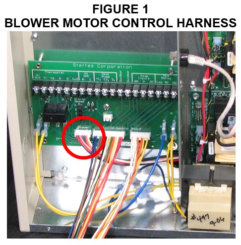
Locate Harness
Locate the blower motor control harness. (See Figure 1.)
Locate Relay Position
Locate an acceptable relay position along the path of the blower motor control harness below the Low Voltage Circuit Board.
NOTE: All connections made with this relay are low voltage. Care must be taken to maintain separation of the low voltage and line voltage circuits.
Mount Relay Base
Mount the relay base in the desired position using the hardware provided.
Cut the Wires passing over the Base
Cut the purple, pink, blue, and green wires from the blower motor control harness as they pass over the relay base.
NOTE: Leave enough slack on both sides of the relay base to insert the new wire ends into the relay base terminal screws.
Wire the Base
Wire the relay base as shown in Figures 2 and 3.

Install Relay
Install the relay on the base.
Energize the System and Verify
Energize the Comfort Plus system and verify the following:
|
Call |
Between 1 and 7 |
Between 2 and 7 |
|---|---|---|
|
G |
24 VAC |
0 VAC |
|
G + Y1 |
0 VAC |
24 VAC |
|
G + Y1 + Y2 |
24 VAC |
24 VAC |
Install Cover
Install the electrical panel cover.