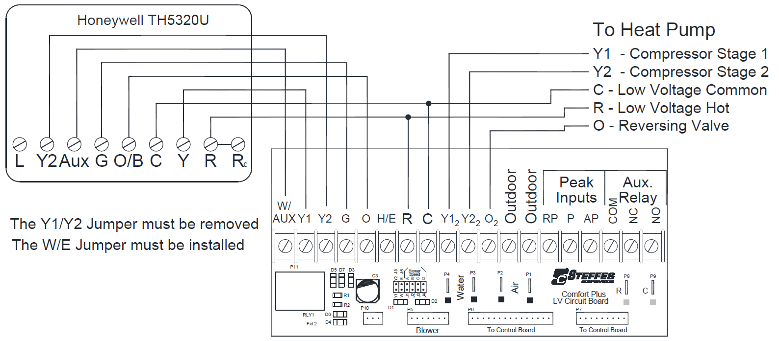
Two Stage Heat Pump Application
|
Thermostat Stage |
Thermostat Output |
Heat Pump Stage |
% of CFM Selected |
Heat Call Status on Digital Display * |
Discharge Air Temperature Target |
|---|---|---|---|---|---|
|
1 |
Y1/G |
1 |
50% or 70%** |
HC1 |
L048 |
|
2 |
Y1/Y2/G |
2 |
100% |
HC1 |
L048 |
|
3 |
AUX/Y1/Y2/G |
2 |
100% |
HC3 |
L049 |
|
Fan |
G |
0 |
600 CFM |
HCF |
N/A |
|
Cool 1 |
Y1/G/O |
1 |
50% or 70%** |
COOL |
N/A |
|
Cool 2 |
Y1/Y2/G/O |
2 |
100% |
COOL |
N/A |
|
Emergency |
H/E |
0 |
100% |
HC3 |
L049 |