THIS PROCEDURE MUST BE PERFORMED BY A QUALIFIED TECHNICIAN.
Item # 1041730R (Core Blower Assembly), 1040403R (Motor Kit), and 1020003R (Wheel)
THIS PROCEDURE MUST BE PERFORMED BY A QUALIFIED TECHNICIAN.
Item # 1041730R (Core Blower Assembly), 1040403R (Motor Kit), and 1020003R (Wheel)
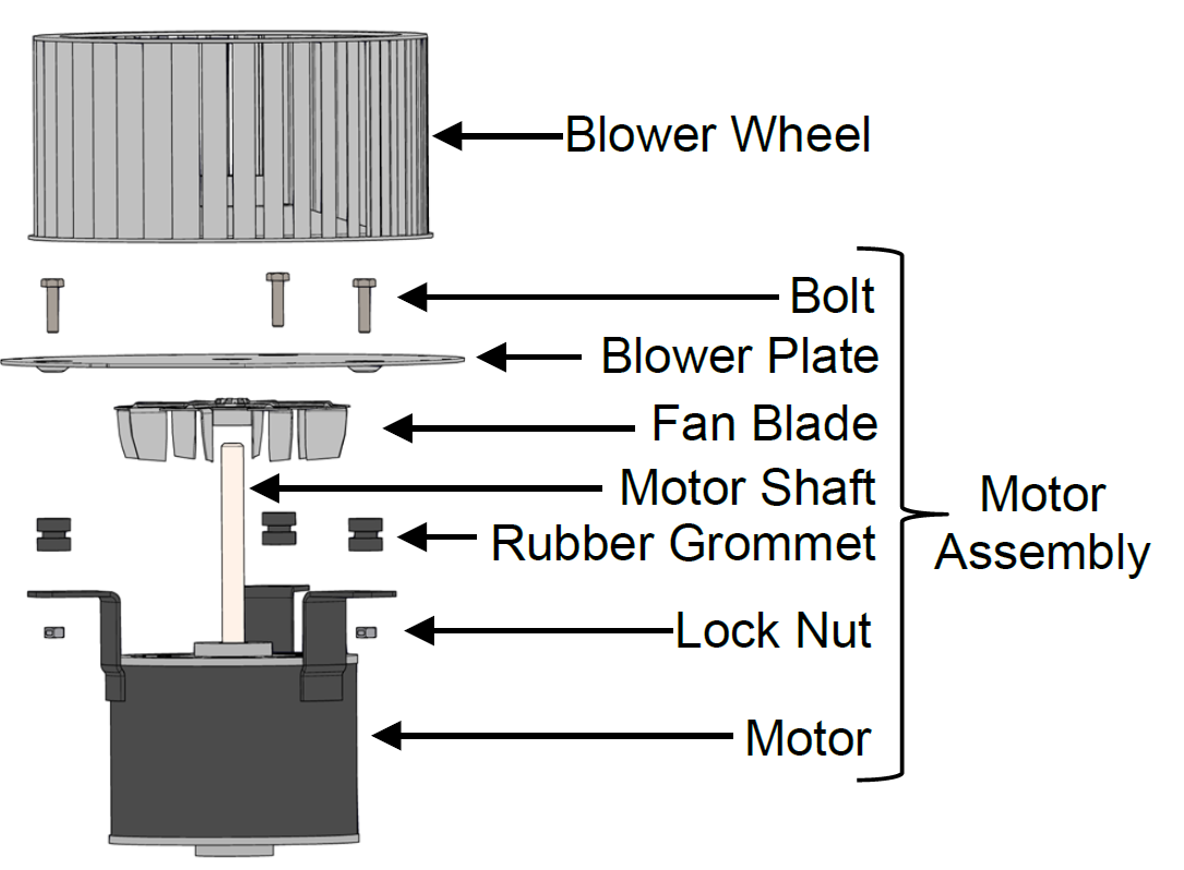
Replacement Motor Kit (1040403R) Includes:
Motor Assembly
Capacitor
Capacitor Boot
Label Fan Motor Direction
Replacement Wheel Kit (1020003R) includes:
Blower Wheel 9 1/8" X 4 1/4"
 WARNING
HAZARDOUS VOLTAGE: Risk of electric shock. Can cause injury or death. Heater may be connected to more than one branch circuit. Disconnect power to all circuits before servicing.
De-energize the system and remove the electrical panel cover.
Remove the two (2) screws from the 75VA transformer (Figure 1) and set aside.
NOTE: Use caution when working inside the electrical compartment of the system as the wiring harnesses can be damaged by sharp edges and mishandling.
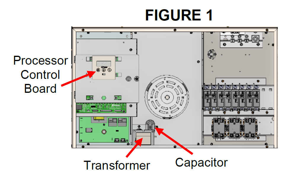

Figure 1
Disconnect the black and white wires from the core blower.
Remove the capacitor (Figure 1) from the electrical panel center insert and disconnect the brown wires. Set the capacitor to the side.
Remove screw and unhinge the processor control board (Figure 1).
Remove the low voltage panel (Figure 2) by taking out the four (4) screws and set aside.
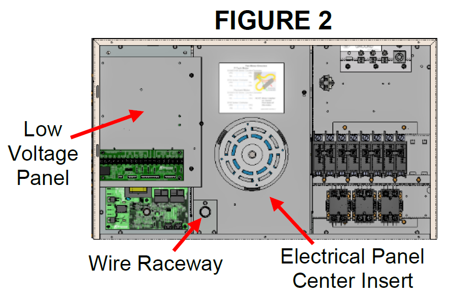
Figure 2
Remove the wire raceway (Figure 2) by taking out the three (3) screws and set aside.
Remove the six (6) screws on the electrical panel center insert (Figure 2) and remove the panel.
Remove the screws securing the core blower assembly (Figure 3). Remove the motor assembly by turning to the side. Make sure the element wires do not get damaged in the process.
NOTE: If replacing entire assembly, go to Step 13.
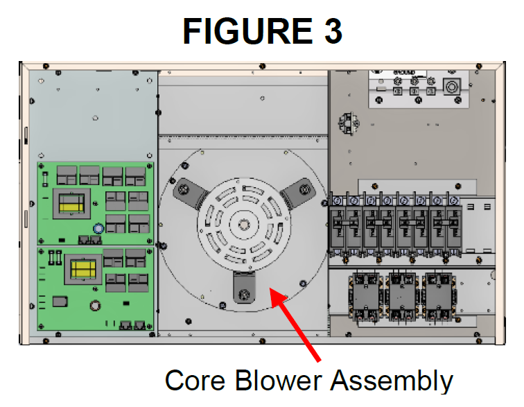
Figure 3
Using a 5/32" Hex wrench, loosen the two (2) set screws on the blower wheel.
Remove the blower wheel from motor shaft.
Slide the new blower wheel onto the motor shaft ensuring the set screws are aligned with the two (2) flat faces of the shaft. Leave 1/4" gap (Figure 4) between the wheel and mounting plate. Tighten set screws to 120 in/lbs.
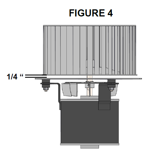
Figure 4
Spin the wheel by hand to ensure the wheel is not touching the blower plate.
Insert new core blower assembly, rotating it so that the flat edge of the core blower plate (Figure 5) is towards the top. The blower motor wiring should be off the lower right side of the motor. Secure in place using previously removed hardware.
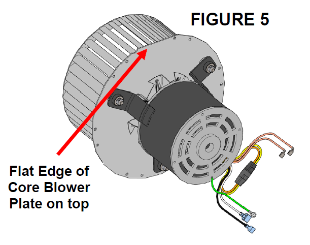
Figure 5
NOTE: Systems built prior to 2007 use a different mounting assembly. Line up holes at 3 and 9 o’clock and secure as needed. See Figure 6.
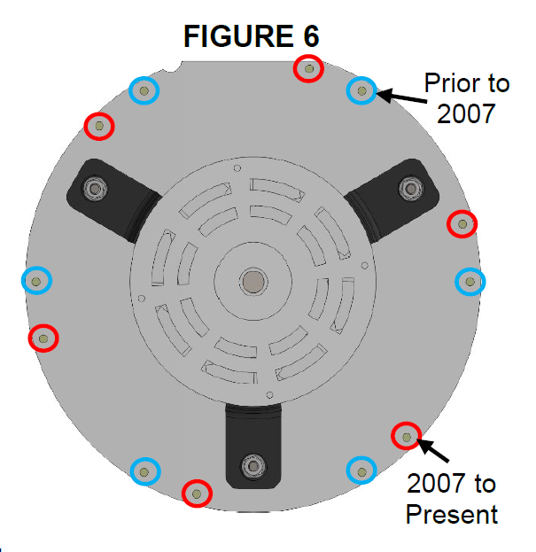
Figure 6
Reinstall the electrical panel center insert back inside the system being careful of all wiring.
Secure the wire raceway
Adhere the Fan Motor Direction label on the panel center insert (Figure 3). Verify reversing connection is correctly selected for the motor install.
Mount the capacitor and attach the ground (green) wire to the electrical panel center insert with the mounting screw.
Slide the rubber capacitor boot onto the brown wires.
Attach the brown wires to the capacitor and secure the boot over the capacitor terminals. Verify the capacitor is correct for the blower motor installed.
| Motor Manufacturer | Capacitor |
|---|---|
| FASCO | 4 mfd, 370V |
| GENTEQ | 4 mfd, 370V |
| PACKARD | 3 mfd, 370V |
| JAKEL/P-TECH | 3 mfd, 370V |
Connect the blue wire from the system to the white wire on the blower.
Connect the black/yellow wire from system to the black wire on blower.
Secure the low voltage panel into place.
Hinge and secure the processor control board into place
Secure the 75VA transformer into place (Figure 1). Verify the jumper ring terminal is secured with the left screw.
Route and secure the core blower wiring in a manner that prevents damage once the system is energized.
Energize the system and verify motor direction.
Reinstall the electrical panel cover and perform system check-out.
1200360 Rev 12 02/14/2025