THIS PROCEDURE MUST BE PERFORMED BY A QUALIFIED TECHNICIAN.
Core Charging High Limit Switch
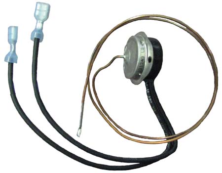
(Manual Reset since June 2013)
This limit monitors temperature along the back panel of the heater and the brick core. If normal operating temperature is exceeded, this limit will interrupt power to the heating elements and the heater's control panel will display "CORE FAIL". If the "CORE FAIL" message occurs repeatedly, verify heater clearances have not been violated and that objects have not fallen between the heater and the wall. If clearances are correct, use the Core Fail flowchart for troubleshooting.
Location: Inside the Back Panel (Extends across Length of the Heater)
Clearance Violation High Limit Switch
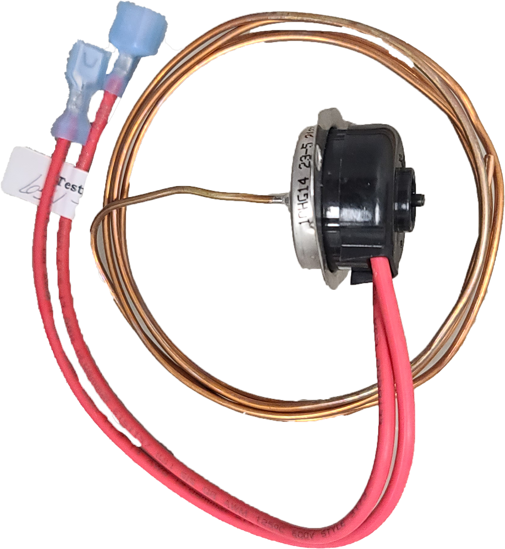
(Manual Reset since June 2013)
This limit monitors temperature along the top panel of the heater and the brick core. If normal operating temperature is exceeded, this switch will interrupt power to the heating elements and the heater's control panel will display "CORE FAIL". If the "CORE FAIL" message occurs repeatedly, verify heater clearances have not been violated and that objects have not fallen between the heater and the wall. If clearances are correct, use the Core Fail flowchart for troubleshooting.
Location: Inside the Top Panel (Extends across front edge)
Discharge Air High Limit Switch
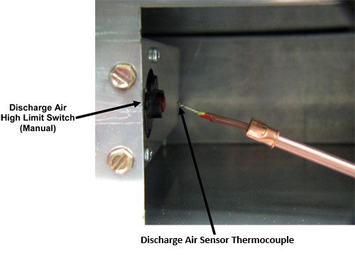
(Manual Reset since June 2013)
This limit monitors discharge air temperature and interrupts power to the control circuit if normal operating temperature is exceeded. This limit switch helps protect against the heating of objects which may obstruct the air discharge area or violate grill clearances. If normal operating temperature is exceeded, this switch will open . When this switch opens, the discharge air system is disabled and the heater’s control panel display will no longer illuminate. To reset the system, press the manual reset button on the limit switch. If the switch opens repeatedly, verify that grill clearances are not violated. If correct, contact a service technician.
Location: Inside the Air Discharge Compartment (Grill Area)
Tip Over Switch
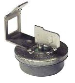
(Heaters equipped with a security base only. Order Item #1024018)
(Auto Reset)
If the heater is not in the upright position, this switch interrupts power to the heating elements and the blower. This prevents the heater from storing heat in or discharging heat from the brick core.
Location: Inside the Electrical Compartment (Mounted on the Back Panel to the Left of the Base I/O Relay Board)
Power Indicator Light
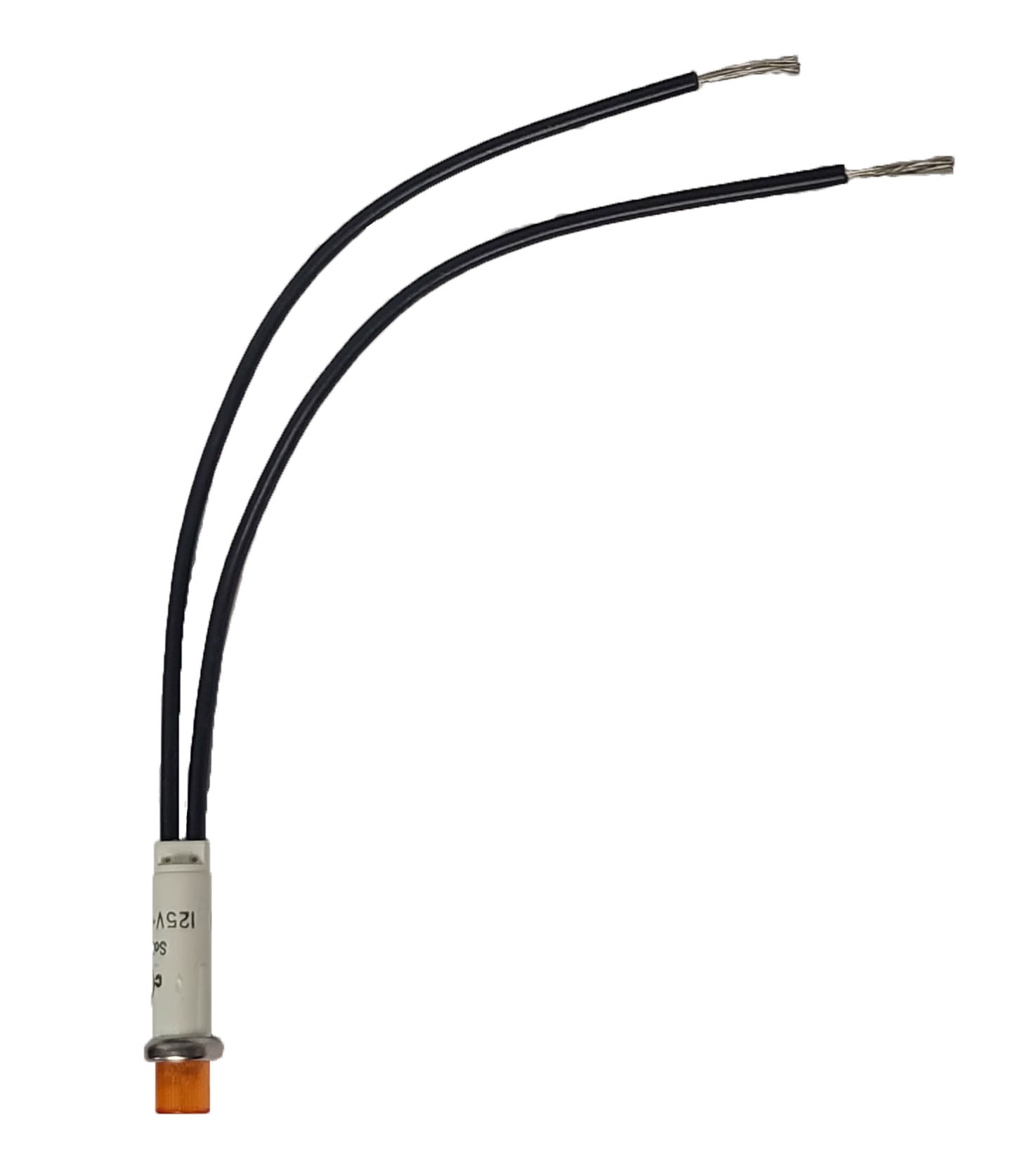
The power indicator light indicates that power is being applied to the heater. Disconnect power to all circuits before installing and/or servicing this equipment.
Location: Lower Right Corner (2100 Series Plug-In Heaters Only)