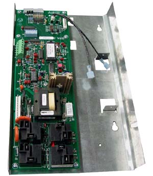
 The control board is the central controller for all functions of the heater. It monitors and controls room temperature and core temperature; it monitors outdoor temperature; and is has a built-in power line carrier receiver.
Inputs
-
Brick Core Temperature Sensor - This is a type K thermocouple that can be read as a hex value in Location 47 (L47). This sensor is connected to the bottom two terminals on the 6 position terminal block at the back of the board. The minimum temperature reading is about 180 degrees Fahrenheit. This thermocouple must not be shorted to ground. Reference the Core Temperature Chart for DC millivolt values.
-
Outdoor Temperature Sensor - This is an NTC thermistor input on the two middle terminals of the 6 position terminal block on the back of the circuit board. Outdoor temperature can be monitored at Location 46 (L46) and will be displayed in a hex value. Reference the Hex Conversion Chart for actual outdoor temperature readings. If using a direct wired outdoor sensor, DIP Switch #6 must be turned on.
-
Room Temperature Sensor - This is an NTC thermistor input on the top two positions of the 6 position terminal block.
-
Power Line Carrier Signal - The 2000 Series heaters can receive power line carrier signals from a Steffes Power Line Carrier Transmitting device. They will only receive on slow channels. From the factory, they can receive on channel 1 or 2. If the heating system is upgraded to Quantum, they can receive on Channels 1-15.
-
Low Voltage inputs for Peak, Anticipated Peak, Setback.
Outputs
-
Element Control Relays - There are two element control relays in the heater. They are either both on or both off.
-
Low Speed Fan Relay - The low speed fan relay provides power to the blower through the fan speed resistor and provides power to the damper system. Reference the Discharge Air System Diagram for more information.