THIS PROCEDURE MUST BE PERFORMED BY A QUALIFIED TECHNICIAN.
The Steffes ½ HP Air Handler is an optional device used to interface the Comfort Plus Hydronic with a centrally ducted heating or cooling system. The Air Handler includes a plenum assembly, supply air blower, water coil, air filter, wiring harness, and hardware kit.
OPERATION
When the Comfort Plus Hydronic system receives a heat call from the air handler’s room thermostat, the primary loop pump (circulator) is energized to circulate water through the heat exchanger. At the same time, the air handler’s pump (circulator) and the supply air blower are energized. The pump circulates the hot water through the air handler’s water coil and the supply air blower extracts the heat from the water in the coil and delivers it to the appropriate heating zone through the ductwork. When connected directly to the Comfort Plus Hydronic system, the air handler also directs heat lost statically into the living space providing automatic static heat recovery. If used with a heat pump, the air handler has the ability to monitor the outlet air temperature and provide comfort modulation as needed.
SPECIFICATIONS
|
Specification |
Value |
|---|---|
|
Maximum Outlet Temperature |
120°F |
|
Maximum Static Pressure |
.75 inches H2O |
|
Maximum Water Coil Output |
60,000 BTU/hr |
|
Maximum A-Coil Size - Front Access |
20"W X 22"H X 21.2"D |
|
Inner Dimensions of A-Coil Area |
21.2"W X 24.25"H X 21.2"D |
|
Voltage |
240/208 VAC |
|
Wattage |
1,130 |
|
Supply Air Blower |
1/2 HP, 60 HZ |
NOTE: If installing a heat pump or air conditioning coil larger than the front access dimensions can accommodate, removal of the filter tray and the top panel may allow the coil to be lowered into place from the top.
WARNING

HAZARDOUS VOLTAGE: Risk of electric shock. Can cause injury or death. Disconnect all remote electric power supplies before installing and/or servicing.
HIGH TEMPERATURES: Risk of burn. Can cause personal injury. Do not install air handler when outer surfaces of the system are hot.
INSTALLATION
De-energize System
De-energize the Comfort Plus Hydronic system and unbox the Air Handler.
Remove Supply Blower Cover
Remove the cover from the supply blower opening (Figure 1) of the Air Handler and locate the hardware kit.
Remove Coil and Filter Covers
Remove coil and filter covers. Then, remove the front panel of the air handler by removing the perimeter screws.
Remove Screw and Position the Coil in Place
During shipping, the water coil is held in place by one screw on the right side panel of the Air Handler. Remove the screw and lower the water coil into place. Secure the water coil with the screws provided in the hardware kit.
Attach Air Handler
Attach the Air Handler to the right side of the Comfort Plus Hydronic system using six of the eight 7/8” silver screws provided in the hardware kit. Refer to Figure 2 for placement of the Air Handler in relation to the Comfort Plus Hydronic system.
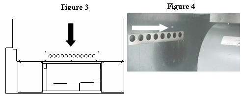
NOTE: For ease in attaching the Air Handler to the Comfort Plus Hydronic system, align the index holes as shown in Figures 3 and 4.
Remove Knockouts
Remove the three knockouts on the front panel of the Air Handler and re-attach the front panel.
 WARNING