THIS PROCEDURE MUST BE PERFORMED BY A QUALIFIED TECHNICIAN.
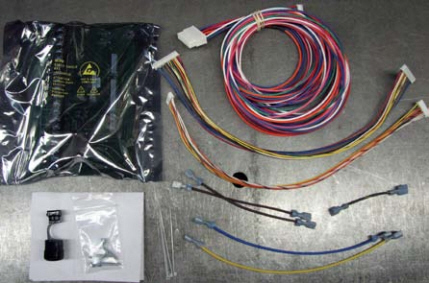
Kit Includes
-
Mounting Screws
-
Connector/Bushing for 7/8” Knockout (90°)
-
Black/Yellow Jumper Wire to Bypass High Speed Relay on Base I/O Relay Board
-
Blue Extension Wire for Transformer Connection to "R" Terminal
-
Yellow Extension Wire for Transformer Connection to "C" Terminal
-
Two Brown Extension wires for Discharge Air Sensor connections to "Air" terminals
-
Low Voltage Motor Control Harness (7-pin to 16-pin)
-
Wire Ties

 WARNING
HAZARDOUS VOLTAGE: Risk of electric shock. Can cause injury or death. Heater may be connected to more than one branch circuit. Disconnect power to all circuits before servicing.
INSTALLATION
Remove Electrical Panel Cover
Remove the electrical panel cover.
Install Jumper Wire
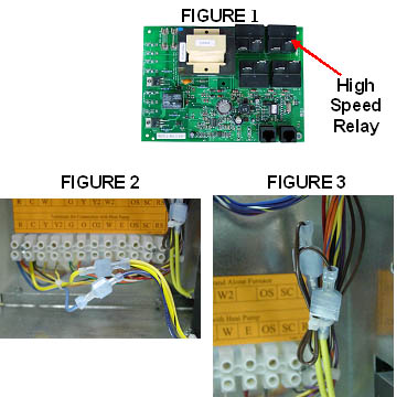
At the base I/O relay board (Figure 1), disconnect the black/yellow and blue/black wires connected to the high speed relay. Install black/yellow jumper wire with two male quick disconnects across these two wires.
Disconnect the Processor Board
Remove the two screws on the left side of the system holding the mounted processor control board (display board) in place. Disconnect the RJ45 interface cable and the two low voltage harnesses (one 9-pin and one 15-pin) and move the processor board out of the way.
Disconnect Blue and Yellow Wires
Disconnect the blue and yellow wires (16 awg) from the "R" and "C" terminals on the 12-position terminal block at the quick disconnects shown in Figure 2.
Disconnect the Brown Wires
Disconnect the two brown wires from "SC" and "RS" at quick disconnects shown in Figure 3.

Disconnect Field Wires
Disconnect field wires from low voltage terminal blocks. Remove and discard the terminal blocks.
Mount Low Voltage Circuit Board
Mount the low voltage circuit board to the new mounting plate with the five 1” x #6 screws provided.
Remove Shipping Bracket
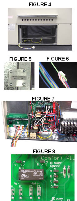
Remove shipping bracket holding the blower in place (Figure 5) and open front blower access panel.
Connect the 9-Pin Harness
Place the supply air blower assembly near the furnace and attach the 9-pin blower wiring harness from the furnace to the 9-pin blower harness (Figure 4) on the supply air blower.
Connect the 16-Pin Harness
Connect the 16-pin end of the low voltage motor control harness to the blower.
Route the 7-Pin Harness
Route the 7-pin wiring harness from the blower assembly into the electrical compartment through the knockout on the lower right corner of the mounting plate.
NOTE: Routing of 7-pin harness is easier if you fish wire (Figure 6) through the electrical compartment and over to the supply air blower plenum.
Connect the 7-Pin Harness
Connect the 7-pin end of the low voltage motor control harness to the “Blower” terminal on the low voltage circuit board.

Connect the Transformer
Connect blue transformer wire to low voltage circuit board “R” terminal and yellow transformer wire to the “C” terminal. Use extension wires as needed.
Connect the Discharge Air Sensor
Connect the yellow discharge air sensor wires to the “Air” terminals using yellow extension wires provided.
Connect 9-Pin and 15-Pin Harness
Connect both the 9-pin and 15-pin wiring harnesses included in the kit to the processor control (display) board and the low voltage circuit board ports labeled “To Control Board”.
Install Supply Air Blower
Install supply air blower assembly to furnace by first attaching the mounting bracket (Figure 4) to the side of the furnace.
Attach the Plenum to the Furnace
Set the blower plenum assembly up on the mounting bracket and attach the plenum to the furnace.
Set Blower Speed
Using the chart below, select proper “Blower Speed". Reference Figure 8 for jumper location.
|
Jumper |
3/4 HP Variable Speed CFM |
|
|---|---|---|
|
A |
1000 |
1200 |
|
B |
1200 |
1400 |
|
C |
1400 |
1600 |
|
D |
1600 |
2000 |
NOTE: Generally, 400 CFM of air flow is recommended per ton of cooling. Therefore, a 3-ton heat pump or air conditioner would require 1200 CFM.
NOTE: If the W/E jumper is in the "OFF" position when installed in a forced air heating system, the blower will NOT run with an "E" call from the thermostat and the core blower will cycle on and off on limit. If receiving a "G" and an "E" call from the thermostat, the system will operate at 400 CFM.
IF installing a Two Stage Heat Pump
If installing the system with a two stage heat pump, the Y1/Y2 jumper must be placed in the “OFF” position.
NOTE: If using a two stage heat pump, a "Y1" signal will yield 70% of the maximum CFM selected. A "Y2" signal will yield maximum CFM selected. Add a relay if 50% Stage 1 airflow is desired.
Connect Outdoor Sensor
Connect the outdoor sensor wires to the “Outdoor” terminals.
IF utilizing Low Voltage Peak Control
If utilizing low voltage peak control, connect the peak control device to terminals “RP” and “P”.