THIS PROCEDURE MUST BE PERFORMED BY A QUALIFIED TECHNICIAN.
 WARNING
HAZARDOUS VOLTAGE: Risk of electric shock. Can cause injury or death. System contains over-sized protective earthing (grounding) terminal, which shall be properly connected.
-
Equipment must be installed by a qualified technician in compliance with all applicable local, state, and national codes and regulations.
-
To ensure proper operation and safety, all line voltage circuits must be segregated from low voltage wiring in the Comfort Plus.
-
To reduce electromagnetic fields associated with electrical circuits and to avoid induced voltage on sensors and electronic devices, the circuit phases MUST be alternated as shown in Figure 12.
-
DO NOT energize the system until installation is complete.
Description
In standard configuration, the system is wired for connection to 240V, however, the element circuits can also be connected to 208V. A 208V connection derates the charging input of the system by 25%. If a system rated specifically for 208V is required, contact the factory. The controls circuit MUST be connected to 240V/208V.
The 60 amp breakers located in the electrical compartment feed the core charging (element) circuits. The 15 amp breaker feeds the controls and blowers circuit. All systems are factory configured to be field connected to multiple line voltage circuits. If a single feed line voltage circuit is desired, an optional single feed kit is available.
To determine the correct wire size required for each circuit feeding the system, refer to the identification label (Figure 11) located on the lower left side of the system.
Route Conductors
Route all line voltage wires through a knockout and into the electrical panel.
Make Connections
Make proper field wiring connections to the system’s breakers. Refer to the Line Voltage Wiring Diagrams on the electrical panel cover for more information on these connections.
NOTE: The 60 AMP breakers on the Comfort Plus are for internal component protection only. Sizing of the field wire and overcurrent protection MUST be in compliance with all applicable local, state, and national codes and regulations.
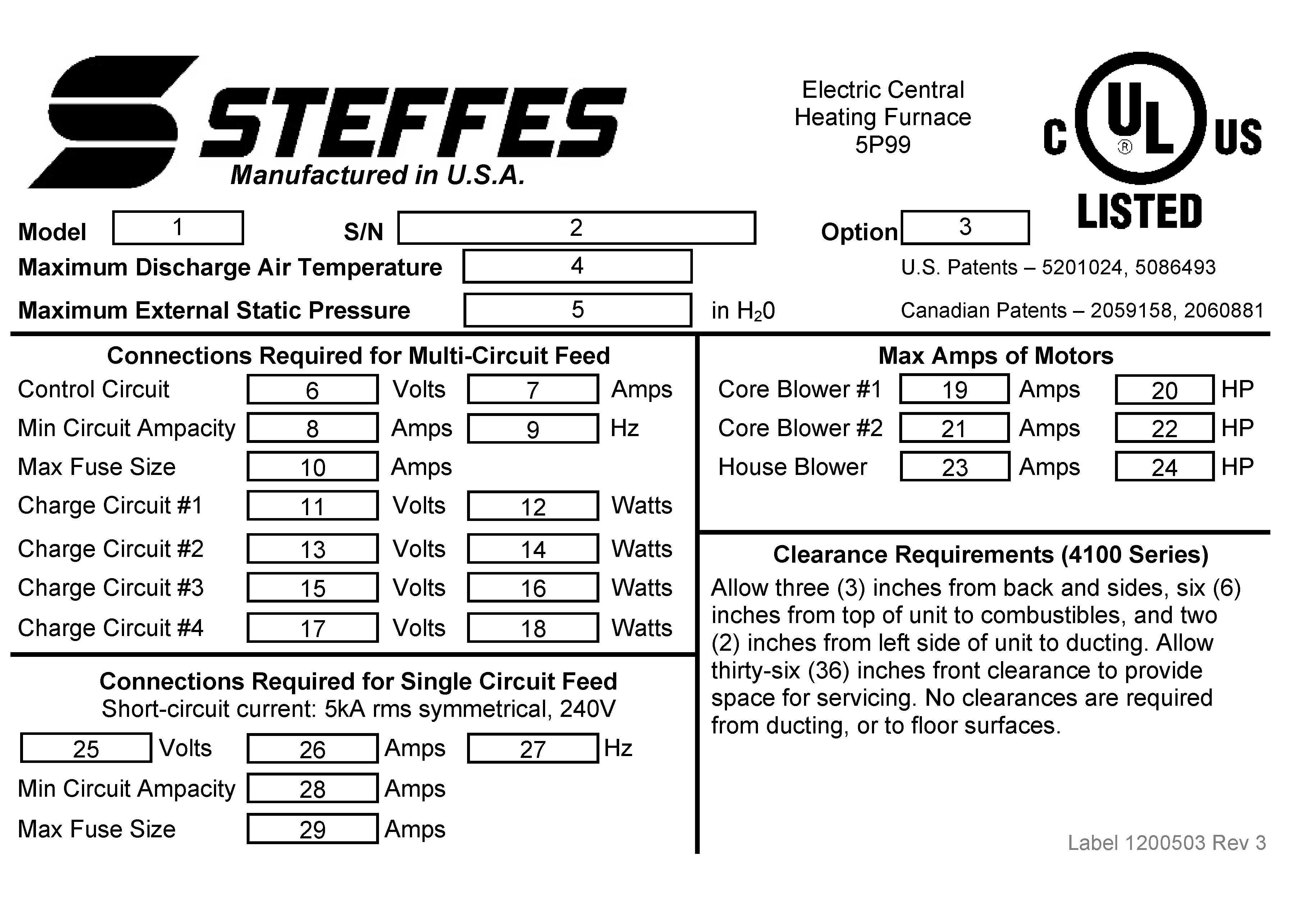

Figure 11 - Sample System Identification Label
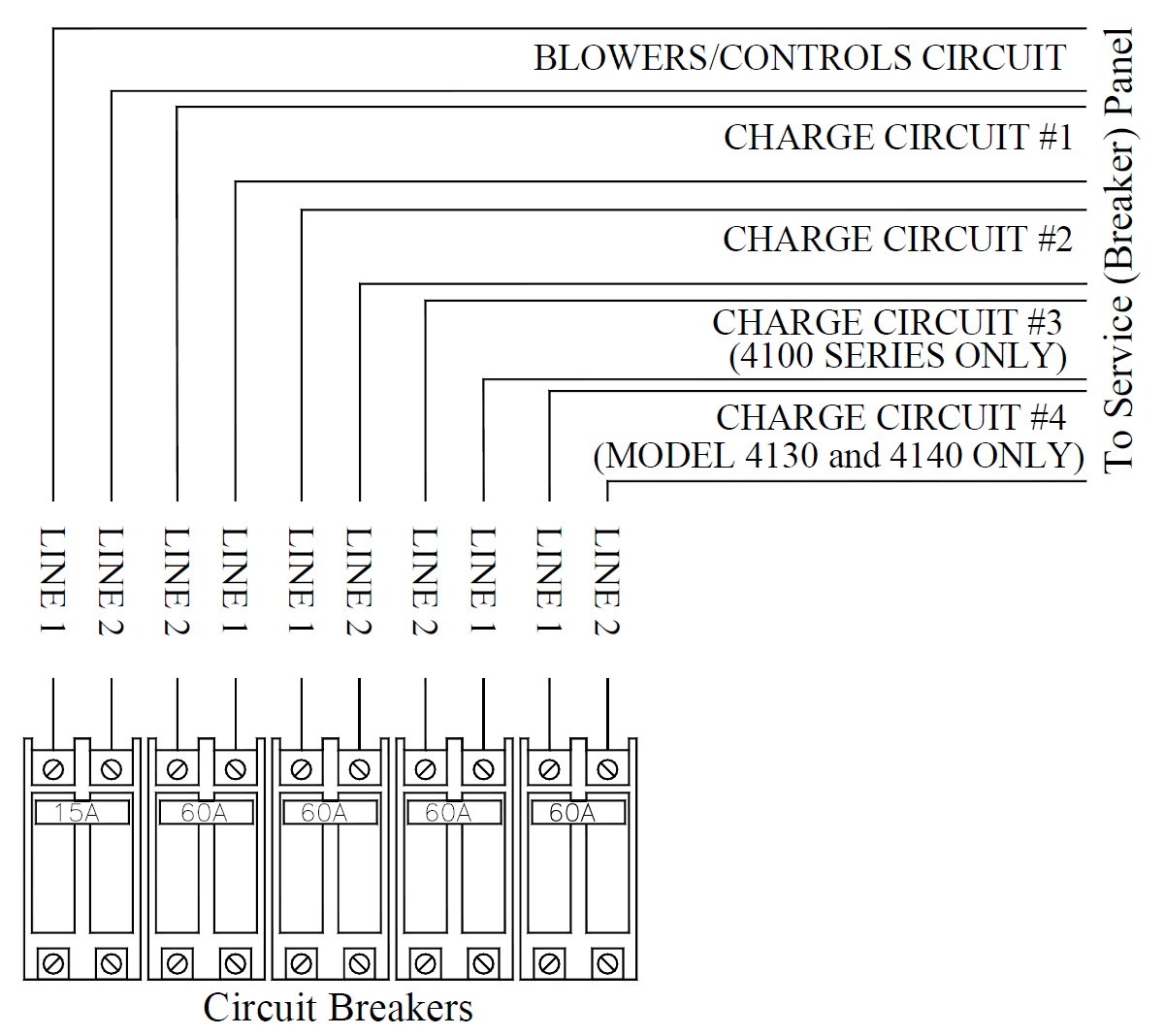
Figure 12 - Circuit Phasing Connections
|
Full Load Current 240VAC only - Circuit deration not included |
|||||
|---|---|---|---|---|---|
| Model | Control Crct | Chrg Crct #1 | Chrg Crct #2 | Chrg Crct #3 | Chrg Crct #4 |
| 4120 - 14.0kW | 7.00 | 21.88 | 21.88 | 14.58 | N/A |
| 4120 - 19.2kW | 7.00 | 30.00 | 30.00 | 20.00 | N/A |
| 4120 - 24.8kW | 7.00 | 38.75 | 38.75 | 25.83 | N/A |
| 4130 - 28.8kW | 7.00 | 30.00 | 30.00 | 30.00 | 30.00 |
| 4130 - 37.2kW | 7.00 | 38.75 | 38.75 | 38.75 | 38.75 |
| 4140 - 38.4kW | 7.00 | 40.00 | 40.00 | 40.00 | 40.00 |
| 4140 - 45.6kW | 7.00 | 47.50 | 47.50 | 47.50 | 47.50 |