THIS PROCEDURE MUST BE PERFORMED BY A QUALIFIED TECHNICIAN.
Item #1021037R-240 Blower 2000/3100/4100 240V Repl (heating systems built before January 2007)
THIS PROCEDURE MUST BE PERFORMED BY A QUALIFIED TECHNICIAN.
Item #1021037R-240 Blower 2000/3100/4100 240V Repl (heating systems built before January 2007)

HAZARDOUS VOLTAGE: Risk of electric shock. Can cause injury or death. Heater may be connected to more than one branch circuit. Disconnect power to all circuits before servicing.
HIGH TEMPERATURE: Risk of personal injury. Internal components and surfaces can be hot. Use caution when servicing the heating system.
NOTE: Both core blowers MUST be replaced with same manufacturer for proper operation.
Disconnect power to all branch circuits of the heating system and remove the electrical panel cover.
Remove the screws holding the transformer (Figure 7) in place and move the transformer to the side.
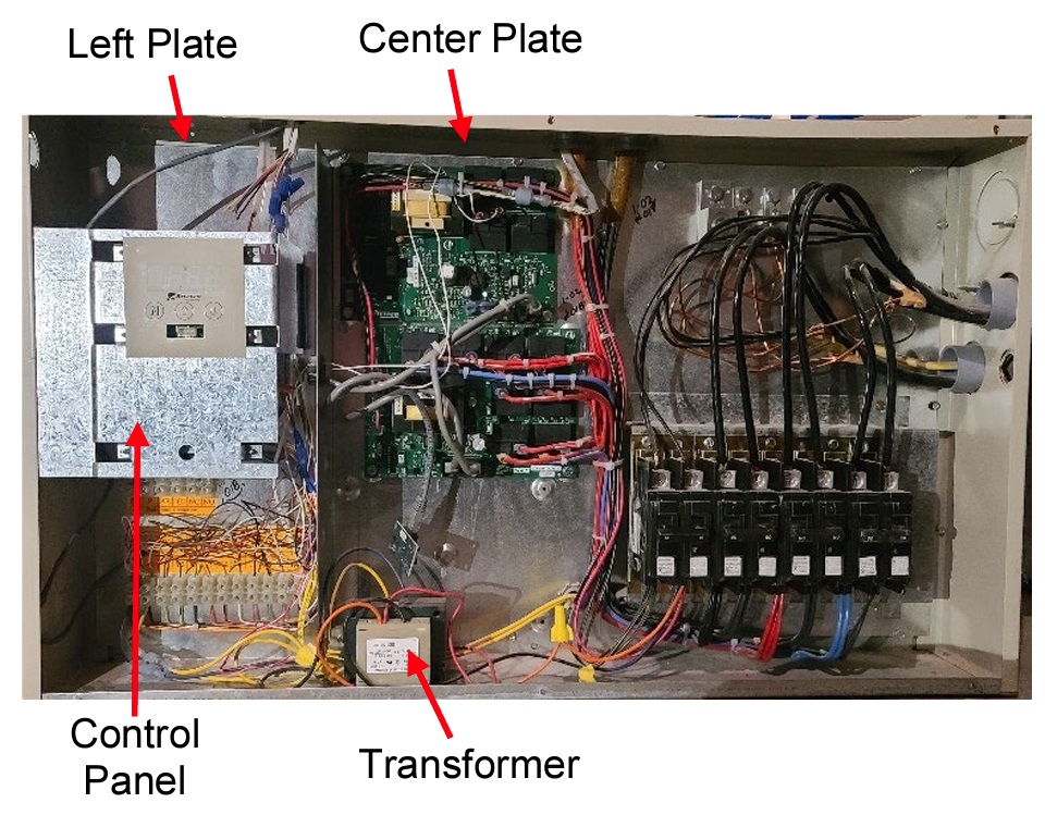
Figure 7
Remove the control panel (Figure 7) from its mounting position and disconnect interface cable from the control board.
Remove the screws around the perimeter of the center plate (Figure 7) of the electrical panel. Move the center plate, with circuit boards attached, to the right of the electrical compartment.
NOTE: Use caution to not damage wiring when moving the plates.
Remove the screws around the perimeter of the left plate (Figure 7) of the electrical panel and set it aside to gain access to the core blowers.
Unhook the springs (Figure 8) holding the core blowers in place and remove the core blowers.
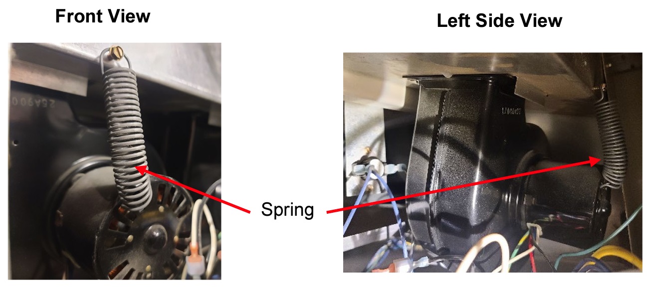
Figure 8
Disconnect the wires to the core blowers and remove blowers for the heater. Mark wires for proper installation of new core blowers.
Connect wires to the new core blowers and place in the base of the heater. Motor faces out to the electrical panel.
Slide blower housing into the sheet metal lip and line up between the divots. Reference Figure 9.
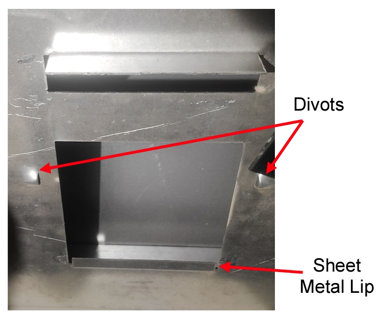
Figure 9
Secure the core blowers with the springs (Figure 8).
Re-install the left and center plates of the electrical panel.
NOTE: Use caution to not damage wiring when moving the plates.
Secure the interface cable to the control board.
Secure the control panel to the electrical panel.
Re-install the transformer, securing the yellow wire with the ring terminal to the left screw.
Secure the electrical panel cover and energize the heater.
Verify Location 94 (L094) is set to the value of 195. If 208V application, Location 28 (L028) must be set to 10. For information on how to access location values, click here.
Complete the system check-out procedure and verify core blower operation.
Document #1200598 Rev 3 02/21/2023