WARNING
Risk of electric shock. Can cause injury or death. This heater may be connected to more than one branch circuit. Disconnect power to all circuits before installing or servicing. DO NOT remove the painted front panel while energized. Equipment must be serviced by a qualified technician.
Risk of fire. Can cause injury or death. ETS devices run for long periods of time at high electrical loads. Poor or marginal connections will cause the connections to overheat and fail.
Check Connections
De-energize the electrical circuit(s) feeding the heater. Place the control circuit board in the service position by sliding it off its mounting screws and hooking it on these same screws using the eyelets provided on the front of the mounting plate. Inspect all field installed electrical connections to ensure they are tight and that all wires are routed correctly. Keep in mind that ETS devices run for long periods of time at high electrical loads. Poor or marginal electrical connections will cause the connection to overheat and fail.
NOTE: Class II (low voltage) wiring or any wiring not rated for line voltage should never be installed in a line voltage area.
Verify Damper System
Check the damper system to ensure the damper operates freely and that there is no debris in this area which could inhibit its operation. To do so, manually press the damper lever extending from the damper assembly. Be careful not to bend the damper actuator. If the damper is not free, remove the blower and clean any debris from that area.
Verify DIP Switches
Check the settings of the DIP switches on the back of the control circuit board. In applications where the heater is being controlled by the power line carrier transmitter, typically all DIP switches will be set in the "OFF" position. If using a hard wired outdoor temperature sensor for automatic charge control, set DIP switch 6 on the back of the circuit board to the "ON" position. With manual charge control, DIP switch 6 must be set to the "OFF" position.
Verify Blower Operation
Energize the heater and check blower operation. If the blower is operating, adjust the room temperature set point below the actual room temperature. To make certain the blower will start in low speed, set the room temperature one degree above actual room temperature. To check to ensure the heater’s blower will operate in high speed, adjust the room temperature set point to at least five degrees above actual room temperature.
Check Charging Circuits
Set the heater to the charge mode and adjust the room temperature so the blower is operating. With a clamp-on amp meter, check for proper amperage draw on the charging circuit(s). On Models 2002 and 2003, this is done at B1 terminal block position. On Models 2004, 2005, and 2006, this is done by totaling the readings from the B1 and R1 terminal block positions. Refer to the Unit Identification Label for information on voltage and input wattage of the heater being installed. Use the Charging Circuit Amperage Draw table for reference to the correct amperage for the specific heater being installed.
Label Panel
Make certain all fuses and/or circuit breakers are labeled in the distribution panel. Use the Steffes orange panel label provided in the wall mounting bracket hardware package.
NOTE: This label is important since the heater may be connected to more than one branch circuit.
Verify Other Controls
Check all other system controls for proper operation.
Close the Heater
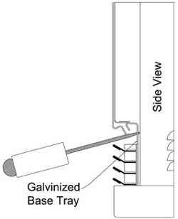
De-energize the heater. Return the control circuit board to its original position. Install the painted front panel. To assist in aligning the front panel with the top panel and to make it easier to install the front panel screws, lifting slots have been provided in the galvanized base tray, one at each end. Place the tip of a screwdriver in one of these slots and lift upward. Install the screw. Do the same on the other end. Be sure to use the plastic grill guard when installing the screws to protect the grill from being scratched. The grill guard should be removed after the installation. Energize the system.
Documentation
Present owner with the manual and warranty information. The owner's registration card must be completed and returned to Steffes to ensure warranty coverage. The owner should retain the top portion of the card for their records. The installer should retain the Supplemental Guide.
Review Operation
Take the time needed to instruct the owner on how to operate the system. Many service calls with new ETS systems are a result of owner confusion on equipment operation. The time spent in training will greatly reduce the chance of a call back.