THIS PROCEDURE MUST BE PERFORMED BY A QUALIFIED TECHNICIAN.
WARNING
HAZARDOUS VOLTAGE: Risk of electric shock. Can cause injury or death. System may be connected to more than one branch circuit. Disconnect power to all circuits before servicing.
THIS PROCEDURE MUST BE PERFORMED BY A QUALIFIED TECHNICIAN.
HAZARDOUS VOLTAGE: Risk of electric shock. Can cause injury or death. System may be connected to more than one branch circuit. Disconnect power to all circuits before servicing.
Disconnect power to the system and remove the painted front panel to gain access to the electrical compartment.
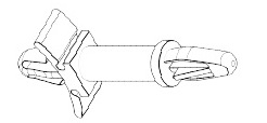
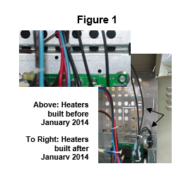
2100 Only - Insert the plastic standoffs into the two holes located above the base I/O relay board at the back of the heater. See figure 1 below.
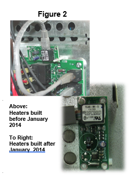
2100 Only - Mount the time clock module onto the plastic standoffs (Figure 2). Module will snap into place.
- Insert one end of the interface cable provided into the interface port on the time clock module.
- Insert the other end of the interface cable into the port labeled "expansion" on the base I/O relay board.
Quantum Only - Tie wrap the time clock module to the existing wiring to hold the module in place.
Re-install the painted front panel and restore power to the system. Configure the system.
Document #1200358 Rev 14 02/02/2024