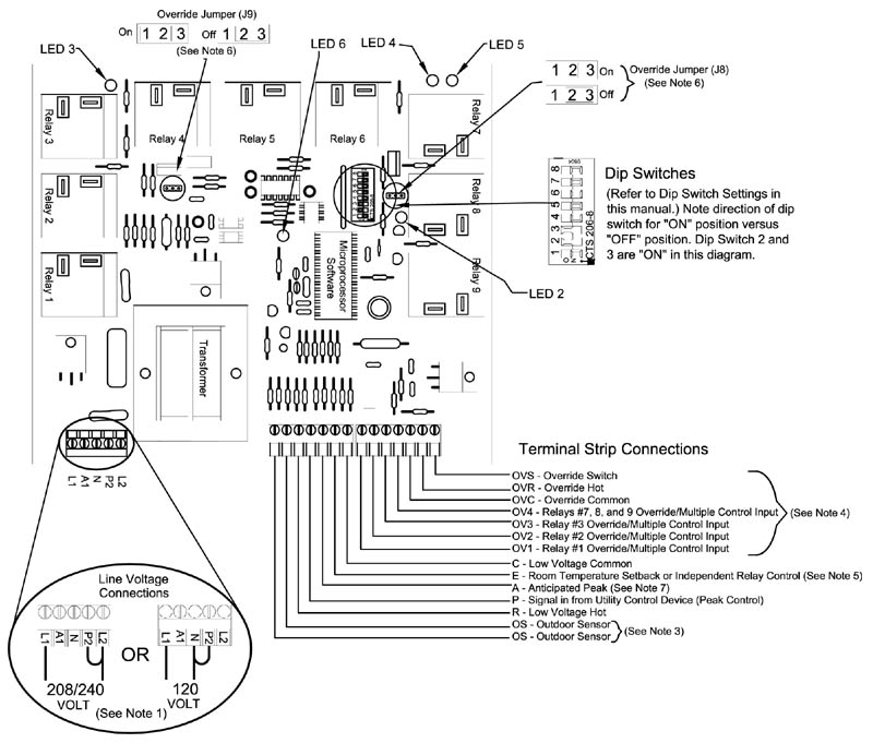
NOTE: For operational information on the green LED lights, see Note 2.
If NOT utilizing the automatic charge control feature of the CCRP, a 4300 ohm resistor must be placed between the two OS terminals to prevent the 2100, 3100, 4100, or 5100 Series heating system(s) from displaying Error 6 (Er 06).
The 4-pole CCRP is configured to utilize relays 1, 2, 3, and 7.