THIS PROCEDURE MUST BE PERFORMED BY A QUALIFIED TECHNICIAN.
Item #1202110
THIS PROCEDURE MUST BE PERFORMED BY A QUALIFIED TECHNICIAN.
Item #1202110
During operation of the Steffes hydronic heating system, some static dissipation comes off the warm outer panels. The Static Heat Recovery unit moves this heat from the hydronic system to the area(s) requiring heat. Utilizing this option helps maximize efficiency when the hydronic system is installed in an area with minimal heating requirements such as a utility room.
With the Static Heat Recovery unit installed, the Steffes hydronic heating system can be set up to turn on with a cooling thermostat connected to R and G (highly recommended) or according to temperature in the brick core. When energized the blower in the Static Heat Recovery unit draws heat from inside the painted outer panels of the system and delivers it to the desired area of the structure.
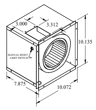
The Static Heat Recovery unit is equipped with a 190°F limit switch to monitor outlet air temperature. If outlet air temperature reaches 190°F, the manual reset limit switch will open, causing the recovery unit to turn off. If this limit switch opens, contact a qualified service technician as this could be an indication of overheating of the system’s brick core.
|
Specification |
Value |
|---|---|
|
Maximum Outlet Temperature |
190°F |
|
Maximum Static Pressure |
0.15" H2O |
|
CFM @ 0.15" H20 |
130 CFM |
|
Voltage |
240/208 VAC 60 HZ |
|
Power |
130W |
|
HP |
.1 |

HAZARDOUS VOLTAGE: Risk of electric shock. Can cause injury or death. System may be connected to more than one branch circuit. Disconnect power to all circuits before installing or servicing. Equipment must be serviced by a qualified electrician.
Hot Surface: Allow to cool before installing and/or servicing the Static Heat Recovery unit.
De-energize the hydronic system.
Locate the indicators on the left side panel and drill 1/8" holes through the eight outer markings as shown in Figure 1.
NOTE: Use caution when drilling to make sure to drill only through the outer painted panel. Drilling too far in can cause damage to the inner galvanized panel and the micropore insulation, causing unsafe operation.
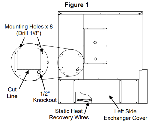
Using the 4 inner indicators on the left side panel, cut a 6.5” X 8” opening along the cut line. Position the opening as shown in Figure 1 to ensure proper operation.
Punch out the ½” conduit knockout on the left side of the system as shown in Figure 1.
Locate the installation hardware kit and install the plastic bushing into the knockout.
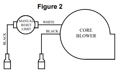
Remove the left side exchanger cover on the heating system. Locate the orange and black static heat recovery wires (Figure 1). Route the orange and black wires through the notch in the top base panel, up to and through the knockout on the left side panel. Connect these wires to the two black wires from the static heat recovery unit. See Figure 2.
Attach the Static Heat Recovery unit to the hydronic system using the screws provided.
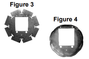
Locate the duct adapter (Figure 3) included with the static heat recovery unit. This adapter provides a transition for connecting to a six-inch round duct. Bend the tabs on the duct adapter up as shown in Figure 4.
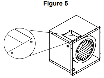
Remove the two screws along the edge of the duct opening on the static heat recovery unit (Figure 5). Place the larger holes of the duct adapter over the two remaining screws and secure the duct adapter in place with the screws previously removed.
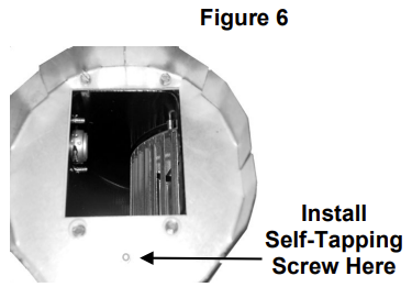
Complete the duct adapter installation by installing the self-tapping screw in the pre-drilled hole on the duct adapter (Figure 6). Connect field ducting to the adapter.
NOTE: Field ducting must be hard pipe. Flex pipe should NOT be used because of the typical temperature rating and the high static pressure associated with flexible duct.
Re-install the left side exchanger cover and energize the system.
Air temperature in the area where the hydronic system is located should be maintained at less than 85ºF/29°C. Steffes recommends installing a low voltage cooling thermostat, connected between R and G, to maintain a temperature of less than 85ºF/29°C. When using the cooling thermostat, set Location 51 (L051) to the maximum setting allowed.
To configure the system to energize the Static Heat Recovery unit at a specific brick core temperature, enter the core temperature at which the blower is energized in Location 51 (L051).
1200366 Rev 11 - 09/25/2024