THIS PROCEDURE MUST BE PERFORMED BY A QUALIFIED TECHNICIAN.
 WARNING
HAZARDOUS VOLTAGE: Risk of electric shock. Can cause injury or death. Heater may be connected to more than one branch circuit. Disconnect power to all circuits before servicing.
-
DO NOT energize the system until installation is complete.
-
DO NOT operate the Comfort Plus Hydronic heating system without the factory supplied junction box in place. Connections to the primary loop pump MUST be made inside the junction box. If installing the optional air handler, the air handler pump connections MUST also be made in the junction box.
-
Equipment must be installed by a qualified technician in compliance with all applicable local, state, and national codes and regulations.
Attach Junction Box
Attach the factory supplied junction box to the left side of the system as shown on the Typical Primary Loop diagram.
Make Connections
Make connections to the primary loop pump and air handler pump inside this junction box. The red and white wires connect to the primary loop pump and the black and white wires connect to the air handler pump. See Figure 10. The maximum connected amperage on either of these circuits is 1.2 amps.
NOTE: If utilizing the optional air handler, the orange wire can be used with the white wire to power a secondary pump for hydronic zones.
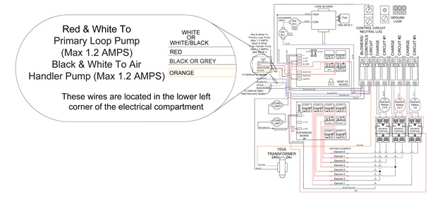

Figure 10 - Line Voltage Wiring Diagram
Attach Junction Box Cover
Attach the junction box cover using the screws provided.