THIS PROCEDURE MUST BE PERFORMED BY A QUALIFIED TECHNICIAN.
WARNING

HAZARDOUS VOLTAGE: Risk of electric shock. Can cause injury or death. System may be connected to more than one branch circuit. Disconnect power to all circuits before servicing. Equipment must be installed and serviced by a qualified technician.
HIGH TEMPERATURES: Risk of personal injury. DO NOT install Air Handler when outer surfaces of the Comfort Plus Hydronic system are hot.
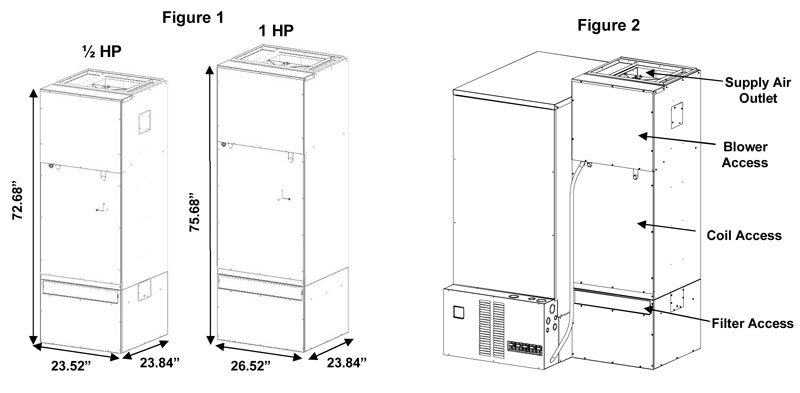
NOTE: Per UL requirements, the air handler must be mounted to the right side of the Comfort Plus Hydronic system. Reference Figure 2.
Important Links are given at the bottom of this topic.
Shut Power Off
De-energize the Comfort Plus Hydronic system and unbox the air handler.
Remove Covers
Remove the blower and coil access covers from the air handler (Figure 2).
Remove Base
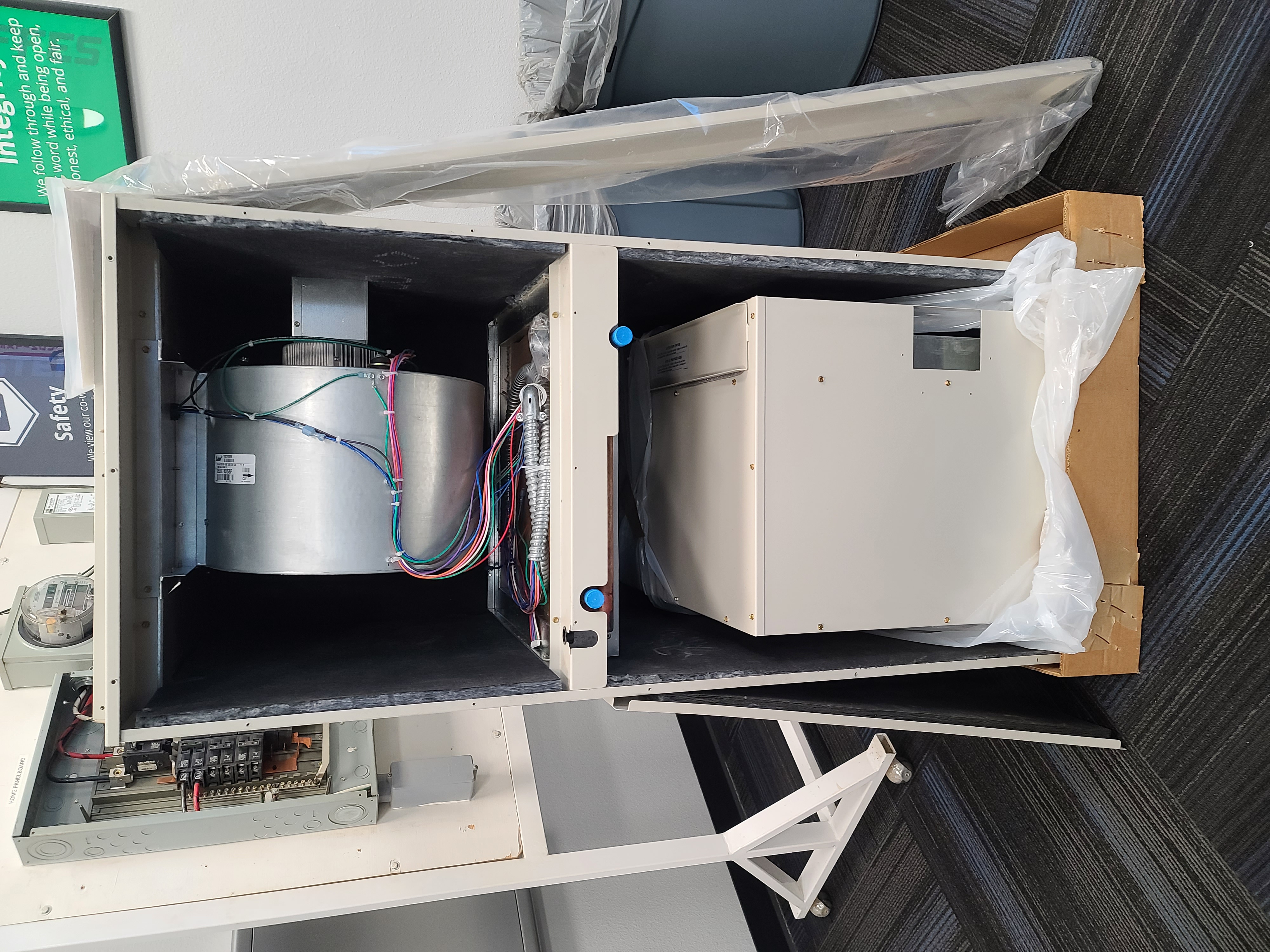
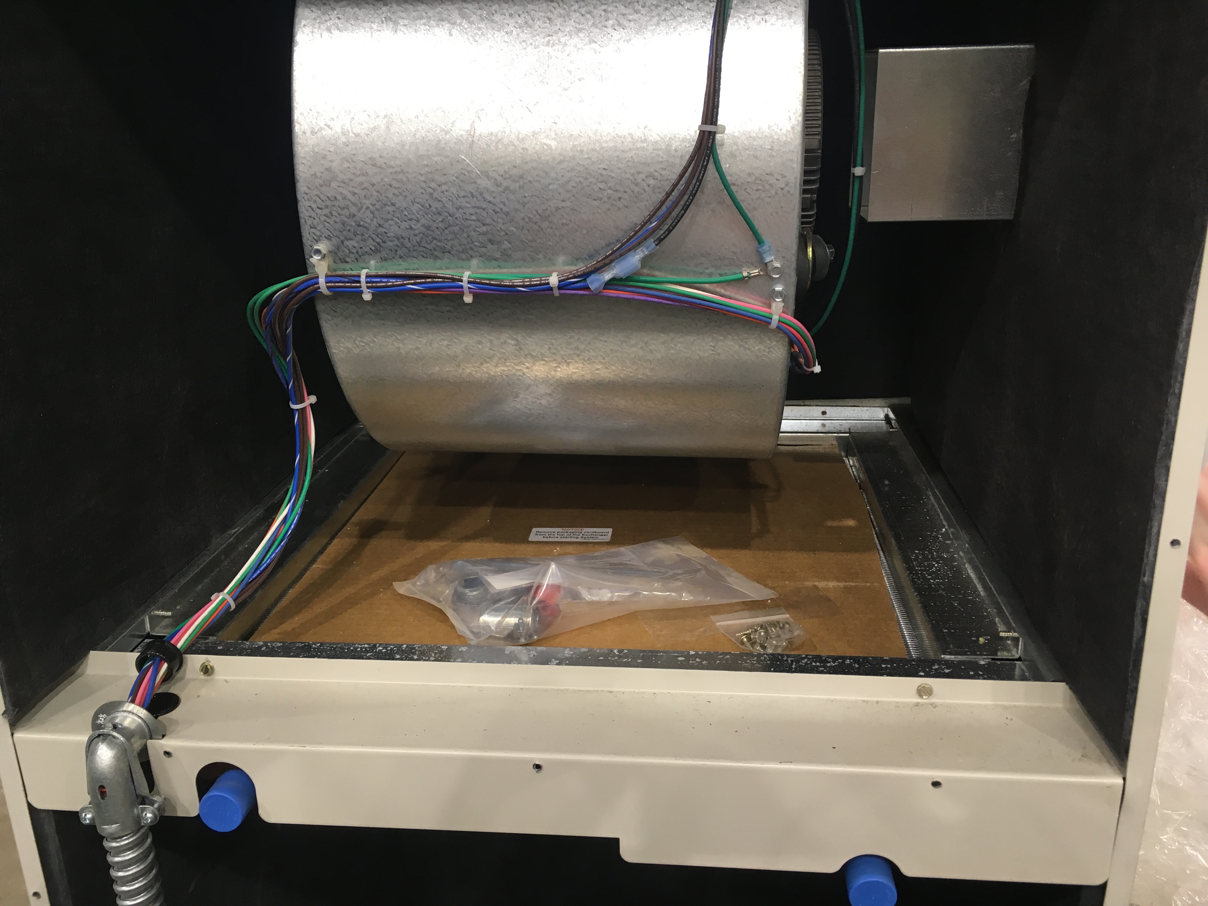
Remove the air handler base from inside the air handler.
Remove Filter, Locate Hardware Kits
Remove the filter from the base and locate the hardware kits.
Mount Base
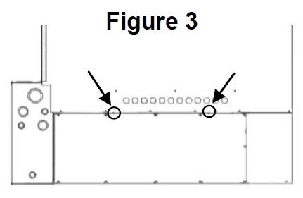
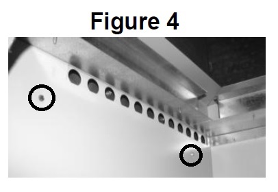
Mount the air handler base to the base of the furnace using the index holes as shown in Figures 3 and 4. Figure 4 is, as viewed, looking up and into the base of the air handler. Screws for attaching the base are included in the hardware kit.
Install Supports
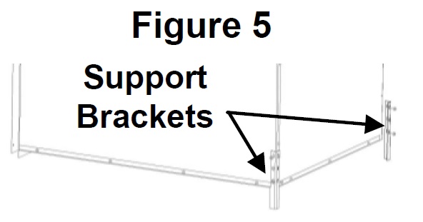
Install support brackets, as shown in Figure 5.
Cut Return Opening
Cut a return opening into the base of the air handler. The return should be sized for the installation and can be cut into any one of the three available sides or the bottom of the air handler base below the filter assembly.
Place Air Handler
Set the air handler onto the air handler base. Attach the two together using eight of the screws provided in the hardware kit. There are two screws per flange.
Attach Air Handler
Attach the side of the air handler to the top of the furnace using the 1” x 22” L-bracket shipped in the supply air outlet and six of the self-drilling screws provided.
Attach Bypass
Attach the cold air bypass to the right side of the air handler. Bypass allows air to cool the motor (Figure 2).
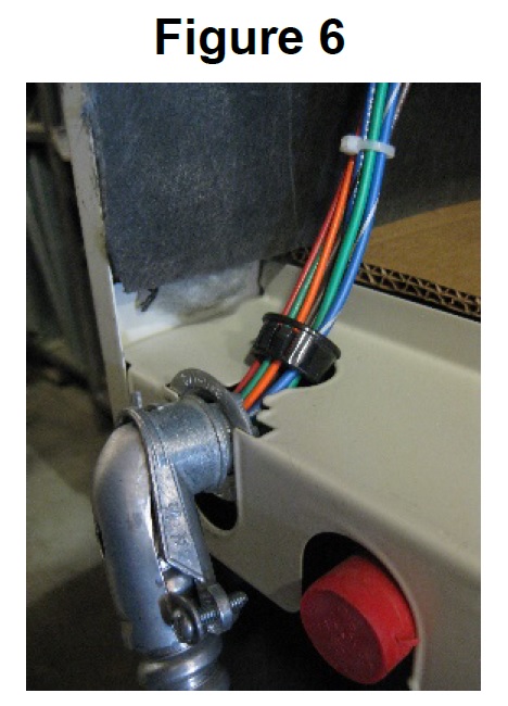
Attach Conduit
Loosen connector nut on flexible conduit approximately 1/8”. Slide connector into slot as shown in Figure 6. The washer and nut must be on the inside of the panel. Snap strain relief bushing into place.
Remove Resistor
Remove the electrical panel cover of the Comfort Plus Hydronic system and locate the air handler wires in the lower right side of the electrical compartment. Remove and discard the resistor connecting the two brown wires.
Route Wiring
Attach the 1/2" flexible conduit connector to the air handler’s umbilical cord and furnace. Reference Figure 8.

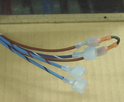
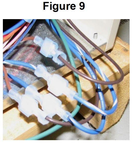
Connect Wires
Connect the wires from the Air Handler to the corresponding colored wires from the Comfort Plus Hydronic system (Figure 9). Connect the green ground wire to one of the sheet metal screws that secure the circuit breaker standoff.
Connect 7-Pin Harness
Connect the 7-pin harness to the port labeled "Blower" on the LV circuit board. (Figure 10).
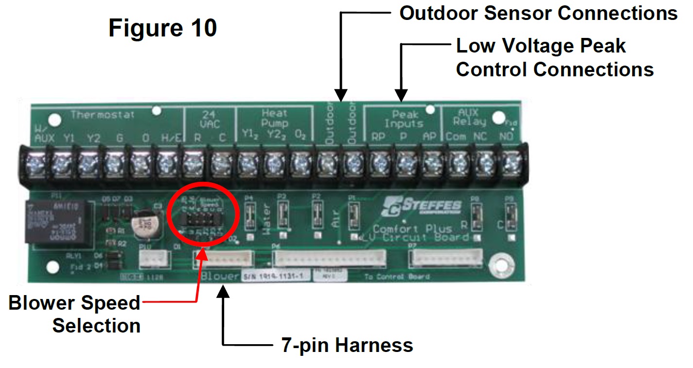
Connect Outdoor Sensor
If an outdoor sensor is used, connect the sensor wires to the "Outdoor" terminals (Figure 10).
Connect Peak Control Wires
If utilizing low voltage peak control, connect the peak control device to Peak Input terminals "RP" and "P" (Figure 10).
Select Proper Airflow
Using the chart below, select the proper "Blower Speed" at the LV circuit board. (See Figure 10).
|
Jumper |
½ HP Variable Speed CFM |
¾ HP Variable Speed CFM |
|---|---|---|
|
A |
1000 |
1200 |
|
B |
1200 |
1400 |
|
C |
1400 |
1600 |
|
D |
1600 |
2000 |
NOTE: Generally, 400 CFM of air flow is recommended per ton of cooling. Therefore, a 3-ton heat pump or air conditioner requires 1200 CFM. See low voltage diagrams in the Links section below.
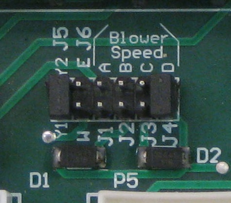
Remove W-E Jumper
The "W-E" jumper MUST be in the "OFF” position.
NOTE: If the W-E jumper is "ON" when installed in a hydronic heating system, the air handler will run with an "H" call from the thermostat. See Room Thermostat Connections Overview.
Set Y1-Y2 Jumper
If installing system with a two stage heat pump, the Y1-Y2 jumper must be placed in the "OFF" position.
NOTE: If using a two stage heat pump, a "Y1" + "G" signal will yield 70% of the maximum CFM selected. A "Y1" + "Y2" + "G" signal will yield 100% CFM selected. If 50% is required, see Links below.
Connect Room Thermostat
Connect field wiring from the room thermostat to the LV circuit board using the appropriate wiring diagram from the Links section below.
Plumbing
See Plumbing Installation topic.
Maintenance
See Air Handler Maintenance and Cleaning topic.