Placement and Clearance Requirements - 4100 Series

yellow triangle with flameWARNING

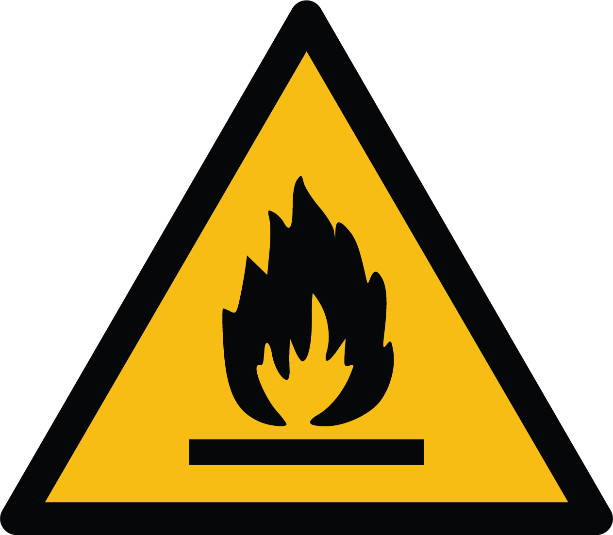
Risk of fire. Can cause injury or death.
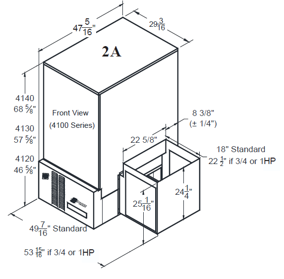
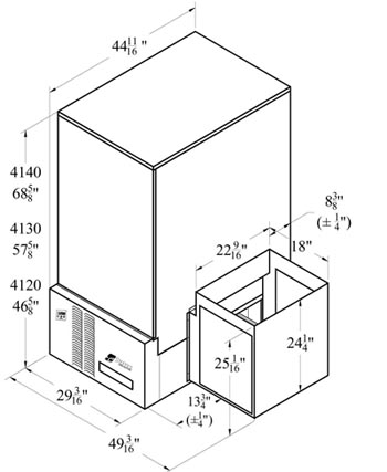
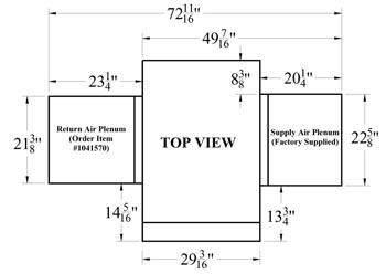
The physical dimensions (Figure 1) of the heating system along with the clearances required (Figure 2) MUST be taken into consideration when choosing its location within a structure.

The best installation location for this system is in a space requiring heat so some amount of the heating requirements can be satisfied through static dissipation from the warm outer panels. In situations where the Comfort Plus is not installed in an area it is intended to heat (i.e. storage closet), it is important to account for the heat lost through static dissipation by making proper adjustments when sizing the system. Standby heat dissipation of up to 2.5kW can be experienced in normal operation. Room air should be maintained at less than 85°F/29°C.

If ventilation is needed, it can be provided by installing a 24” x 24” opening into the area where the Comfort Plus is located. In addition, a 6” x 6” non-closing type register can be cut into the return air duct of the system to minimize heat build-up in the room. This register must be installed in a manner that ensures the air drawn into the heating system passes through the filter first (see Figure 1).

In addition to the physical space requirements, the weight of the system must be taken into consideration when selecting the installation surface. A level concrete floor is the best installation surface, but most well supported surfaces are acceptable. If unsure of floor load capacity, consult a building contractor or architect.

NOTE: Special requirements need to be considered if placing the system in a garage or other area where combustible vapors may be present. Consult local, state, and national codes and regulations to ensure proper installation. An 18" stand (Order Item #1301585) is available to elevate the system.

Clearance Requirements

Three inches (3”) from back, six inches (6”) from top, and two inches (2”) from left side to ducting. Allow thirty-six inches (36”) from front for servicing. No clearances are required from ducting, right side to ducting, or to floor surfaces. Combustible materials must remain at least three inches (3”) from sides, front, and back.

NOTE: Clearance requirements do NOT account for required working space for electrical connections.

zoom in on pictureopen image

Figure 2A - Front View

zoom in on pictureopen image

Figure 2B - Top View

Dimensions

front isometric view of 4100 showing unit dimensionszoom in on pictureopen image

Figure 1A - Base

front isometric view of 4100 showing unit dimensionszoom in on pictureopen image

Figure 1B - Top View

front isometric view of 4100 showing unit dimensionszoom in on pictureopen image

Figure 1C - Isometric View

NOTES:

  • IMPORTANT: Return air duct MUST NOT enter from the front or back of the furnace. Upflow, downflow, or straight return ducting only.
  • Beginning July 1, 2019, the electrical panel became 2 1/2" deeper to accommodate the Definite Purpose Contactors. The overall depth changed from 44 11/16" to 47 4/16", the setback to the return air plenum changed from 14" to 16 1/2", the setback to the supply air plenum changed from 13 3/4" to 16 1/4".

Non-Current: 1/2 HP Motor before DPC

view of psc-style 4100 showing unit dimensionszoom in on pictureopen image

Front View before DPC

front isometric view of 4100 showing unit dimensionszoom in on pictureopen image

Top View before DPC

4100 Install Guide 1206147 Rev 0