THIS PROCEDURE MUST BE PERFORMED BY A QUALIFIED TECHNICIAN.
Item #1301578 (Kit Down Flow 4100 Series)
THIS PROCEDURE MUST BE PERFORMED BY A QUALIFIED TECHNICIAN.
Item #1301578 (Kit Down Flow 4100 Series)
 WARNING
HAZARDOUS VOLTAGE: Risk of electric shock. Can cause injury or death. Heater may be connected to more than one branch circuit. Disconnect power to all circuits before servicing.
NOTE: In down flow configuration, the furnace must be installed in a fashion that allows access to the supply blower’s plenum cover. It is recommended to elevate the furnace a minimum of 10” to achieve this access. An elevation stand (part #1301585) is available from the factory.
Remove the supply air blower plenum assembly from its box.
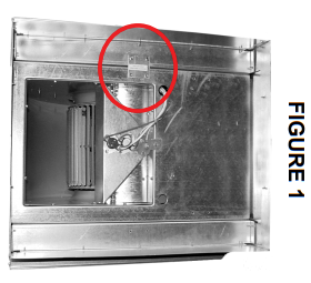
The supply air blower is secured to the plenum by a metal plate used to prevent the blower from moving during shipping. Remove and discard the metal plate (Figure 1).
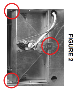
Remove the three screws securing the limit switch bracket to the blower tray (Figure 2).
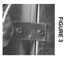
Attach the extension bracket to the blower tray (Figure 3).
Attach the limit switch bracket to the extension bracket (Figure 4).
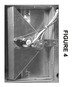
Using the self-drilling screws provided, secure the front two bends of the limit switch bracket to the blower assembly. Be sure tabs of the bracket are flush with the top of the blower assembly tray. Reference Figure 4.

Place the two down flow plenum rails, one on each side, over the existing plenum rails. Secure the rails through the pre-punched holes with the self-drilling screws provided. This provides the blower track when the plenum assembly is rotated for down flow. Reference Figure 5.
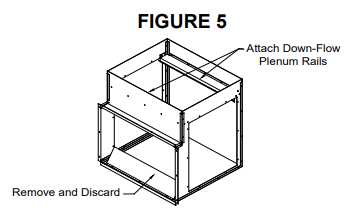
Remove and discard the deflector (Figure 5) mounted to the bottom panel of the plenum.

Remove one of the access doors and slide the supply air blower from the plenum assembly.
Using the gold screws provided, attach the down flow plenum support bracket to the supply air side of the heating system through the factory pre-punched holes.
Attach the down flow deflector to the back support leg on the discharge air side (blower side) of the heating system. Make sure the bottom “V” notch of the deflector cradles the base deflector panel of the heating system. Reference Figure 6.
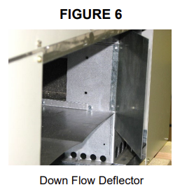
NOTE: The down flow deflector panel MUST be installed on the supply side of the furnace.
Using three of the self-drilling screws provided, attach the plenum to the down flow support bracket by screwing through the pre-drilled holes on the top of the plenum and into the support bracket.
Secure the supply air blower plenum to the heating system through the pre-drilled holes on the sides of the plenum using self-drilling screws provided.
Install the blower into the plenum assembly.
Connect the supply blower wiring harness, located in the base of the heating system, to the blower. Place any excess wiring in the base of the heating system below the radiant heat shield. Verify that the blower is installed in the plenum with the motor facing away from the heating system.
Re-install the plenum access door and complete installation of the heating system as directed in the Owner’s and Installer’s Manual.
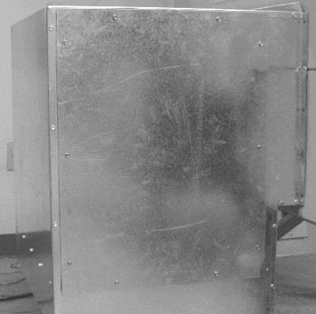
Example of a Typical Plenum Installation in a Down Flow Application
1200356 Rev 5 - 04/26/2023