THIS PROCEDURE MUST BE PERFORMED BY A QUALIFIED TECHNICIAN.
This procedure applies to the following part numbers:
 WARNING
HAZARDOUS VOLTAGE: Risk of electric shock. Can cause injury or death. Heater may be connected to more than one branch circuit. Disconnect power to all circuits before servicing.
What's Included:
-
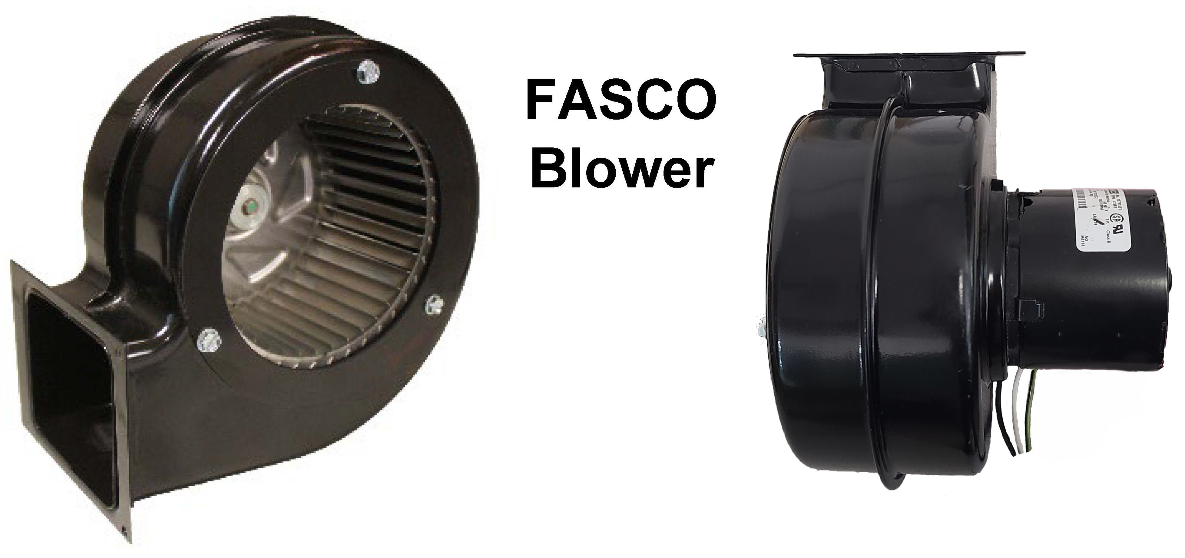
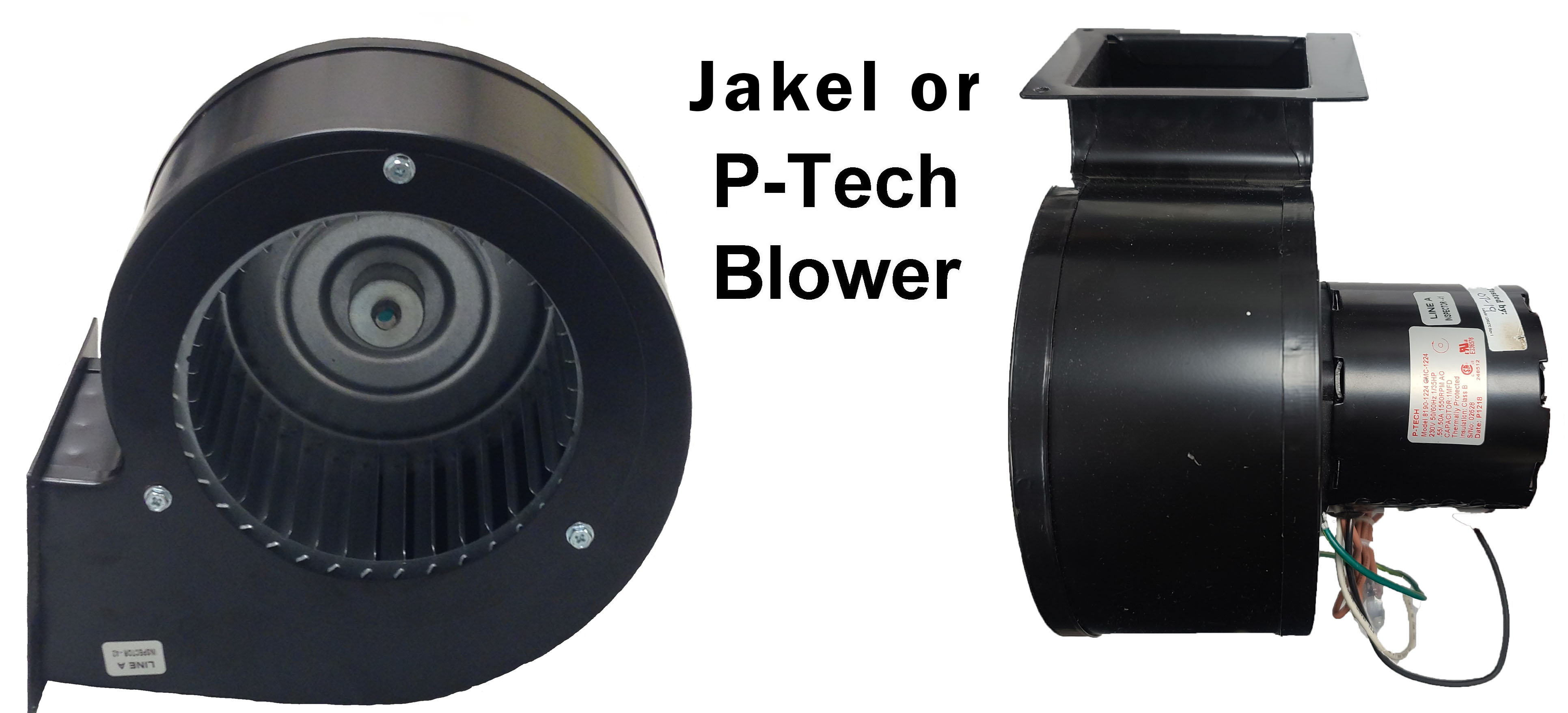
Blower
-
1500 Ohm 50 Watt Resistor (2100 Series 240V Only)
-
250 Ohm 50 Watt Resistor (Model 2102-2103 120V Only)
NOTE: When replacing a blower in a 2100 Series heater, it is important to make sure the blower resistor is correct for the application. Read and follow instructions carefully to ensure proper installation and operation.
Disconnect Power
Disconnect power to all branch circuits of the heater.
Remove Painted Panel
Remove painted front panel by removing the screws located on the bottom edge of the painted front panel.
Hinge the Right Side Panel
Hinge the right side panel open by a) removing the screw located above grill slats on the lower right side of the heater; b) loosening the screw located at top right corner of the electrical compartment; and c) pushing out on the right side panel. Reference Figure 1.
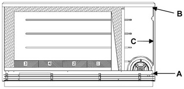
Figure 1
Disconnect Black Wire
At the base I/O relay board (Figure 2) in the back of the heater, disconnect the black wire from the “Blower” terminal.
240V Application Shown Below
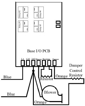
Figure 2
Disconnect White Wire
Disconnect the white blower wire from the white/blue jumper wire attached to L2 120 or L2 240 (depending on the application).
Disconnect Ground
Disconnect the green ground wire from the back, right side of the electrical compartment.
Remove Screw
Remove the screw holding the blower in place (Figure 3) and remove the existing blower.
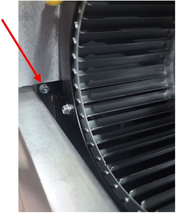
Figure 3
Clean Chamber
Inspect and clean blower opening and damper actuator.
Install New Blower
Insert the new blower and secure into place with the screw (Figure 3).
Connect Ground
Reconnect the green ground wire.
Connect Wires
Connect the black blower wire to the “Blower” terminal on the base I/O relay board. Connect the white blower wire to white/blue jumper.
Check Resistor
Check the ohm value of the blower resistor in the heater. Blowers manufactured by different companies require different resistors. See table below for information on the resistor required for the application:
| Blower Mfg | Input Voltage | Blower Speed Resistor Required |
|---|---|---|
| FASCO | 120V | 150 Ohm 50W |
| FASCO | 208/240V | 600 Ohm 50W |
| Jakel or P-Tech | 120V | 250 Ohm 50W |
| Jakel or P-Tech | 208/240V | 1500 Ohm 50W |

Replace Resistor
If necessary, replace the blower resistor (Figure 4).
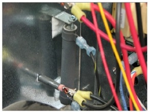
Figure 4
Check Locations
Once the resistor value is verified, check the following locations and make sure they are set properly for the correct resistor. Click here for more information on how to access location values.
| Blower Speed Resistor Required | L028 | L094 | L095 |
|---|---|---|---|
| 150 Ohm 50W | 1 | 220 | 150 |
| 600 Ohm 50W | 240V = 1 208V = 5 | 220 | 150 |
| 250 Ohm 50W | 1 | 240 | 100 |
| 1500 Ohm 50W | 240V = 1 208V = 10 | 240 | 100 |
Reattach Front
Reattach the right side panel and reinstall the painted front panel.
Check Operation
Restore power to the heater and verify blower operation.