THIS PROCEDURE MUST BE PERFORMED BY A QUALIFIED TECHNICIAN.
Item # 1159044R (1000/2000 Series Damper Control Circuit Board)
Item #1040388R (2000 Series Output Temperature Sensor Circuit Board)
THIS PROCEDURE MUST BE PERFORMED BY A QUALIFIED TECHNICIAN.
Item # 1159044R (1000/2000 Series Damper Control Circuit Board)
Item #1040388R (2000 Series Output Temperature Sensor Circuit Board)
 WARNING
HAZARDOUS VOLTAGE: Risk of electric shock. Can cause injury or death. Heater may be connected to more than one branch circuit. Disconnect power to all circuits before servicing.
De-energize the heater and remove the front panel. Place the main control circuit board in the service position by sliding it off its mounting screws and hooking it on these same screws using the eyelets provided on the front of the circuit board mounting plate.
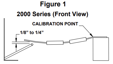
Check the clearance between the damper actuator and the lever extending from the damper assembly. The damper actuator should be on top of the lever. With the resistors cool, there should be a 1/8” – 1/4” gap between the damper actuator and the lever. Calibrate, if necessary, by bending the actuator near its mounting point. (Figure 1)
Inspect the blower and clean if necessary. It is recommended to clean the blower when the heater is cool to the touch.
Check damper operation to ensure optimum performance of the heater. Check damper operation by manually pressing the damper lever down and then slowly raising it. If the damper is not free, remove the blower and clean any debris from the damper area.
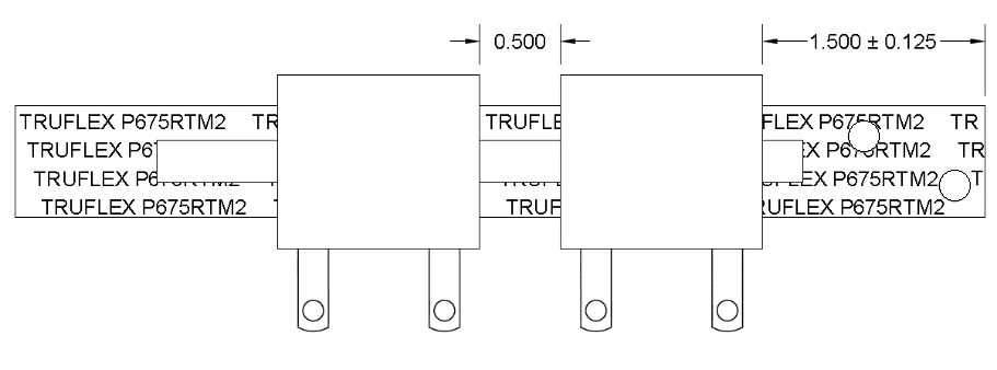
Verify damper resistor spacing as shown:
Energize the heater. Check blower operation as follows:
NOTE: Repeat Steps A and B. A blower that struggles to start in low speed can cause the discharge air temperature to get too hot, causing the output sensor to open.
Verify that the ohm value on the blower resistor is correct for the application. Reference the Blower Resistor Ohm Value Table for more information.
BLOWER RESISTOR OHM VALUE
(All resistors are 50 Watt)
|
FASCO |
|||
|---|---|---|---|
|
Model |
120V |
208V |
240V |
|
2002 |
150 Ohm |
600 Ohm |
600 Ohm |
|
2003/2004 |
125 Ohm |
500 Ohm |
500 Ohm |
|
2005/2006 |
100 Ohm |
400/500 Ohm |
400/500 Ohm |
|
P-TECH |
||
|---|---|---|
|
Model |
120V |
240/208V |
|
2000 Series |
250 Ohm |
1100 Ohm |
NOTE: Refer to the Unit Identification Label on the left side of the heater to determine heater voltage.
A 500 Ohm 50 Watt resistor can be used as a replacement in the 240V Model 2005 and 2006. It will slightly reduce low fan speed on these systems.
CautionRisk of electric shock. Can cause injury or death. Use care when measuring voltage on system components. Failure to use caution can result in equipment damage and/or personal injury or death.
Verify that input voltage exists between “F” and “B” quick disconnect terminals on the damper control circuit board when a heat call is present.
De-energize the heater. Disconnect the orange wires from the damper control circuit board. Check the ohm value across the orange wires. On 240V heaters the ohm value should be 800 ohms; on 120V heaters it should be 200 ohms; and on 208V heaters it should be 600 ohms. If the ohm value is incorrect, replace the damper actuator.
Reconnect the orange wires to the damper control circuit board. Re-energize the heater. Initiate a heat call by adjusting room temperature setpoint up. The blower should run. Check voltage between the orange wires. This reading should be between 50 VAC and 145 VAC for 240V heaters; between 25 VAC and 75 VAC for 120V heaters; and between 40 VAC and 125 VAC for 208V heaters. If incorrect voltage, replace the damper board.
Adjust the room temperature setpoint below actual room temperature to end the heat call. Check voltage across the “F” and “B” terminals on the damper board. With NO Heat call, the voltage should be zero (0). If voltage exists, verify internal system wiring (specifically, that there are no wires connected to the lower left relay on the main processor control board).
Disconnect the yellow wire from the damper control circuit board. Check voltage between the two orange wires once again. With a heat call, the voltage should read less than five (5) volts. If incorrect voltage, replace damper board
De-energize the heater. Reconnect the yellow wire to the damper control circuit board.
Return the main circuit board to its original position and install the heater’s front panel. Restore power to the heater.
1209016 Rev 8 12/2/2024