Discharge Air Sensor - 5100 Series Air Handler
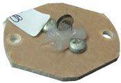
The discharge air sensor is located at the top of the supply air blower assembly near the supply air blower limit switch. This Processor Control Board uses this sensor to monitor discharge air temperature and regulates the variable voltage output to the Air Handler Circulator to maintain a constant, comfortable outlet temperature.
The system maintains two discharge air temperature targets. The lower temperature is Location 48 (L048/C010), which is factory set at 90°F and the system will target this setting any time there is a Stage 1 heat call and the heat pump is not locked out. If there is a Stage 2 heat call or if the heat pump is locked out for any reason, the Comfort Plus system will target a discharge air temperature of 120°F as set in Location 49 (L049).
The discharge air sensor is wired to the processor control board. The two brown discharge air sensor wires run from the air handler to the quick disconnect terminals under the circuit breakers and then over to the ECM Interface Board terminals marked "Air". A reading below 25°F or above 175°F will be indicated at the processor board by a display of Er04 (Error 4, see flowchart).
To test the discharge air sensor, disconnect one brown wire and take an ohm reading across the sensor and compare it to the Temperature Sensor Resistance Graph and the value in Location 112 (L112). The value in Location 112 indicates the current discharge air temperature as read by the processor control board. If the resistance is low or the sensor reading is high, clean the sensor and try again. Use a cleaner safe for electronics, such as rubbing alcohol.