Part #19 - 4200 Series
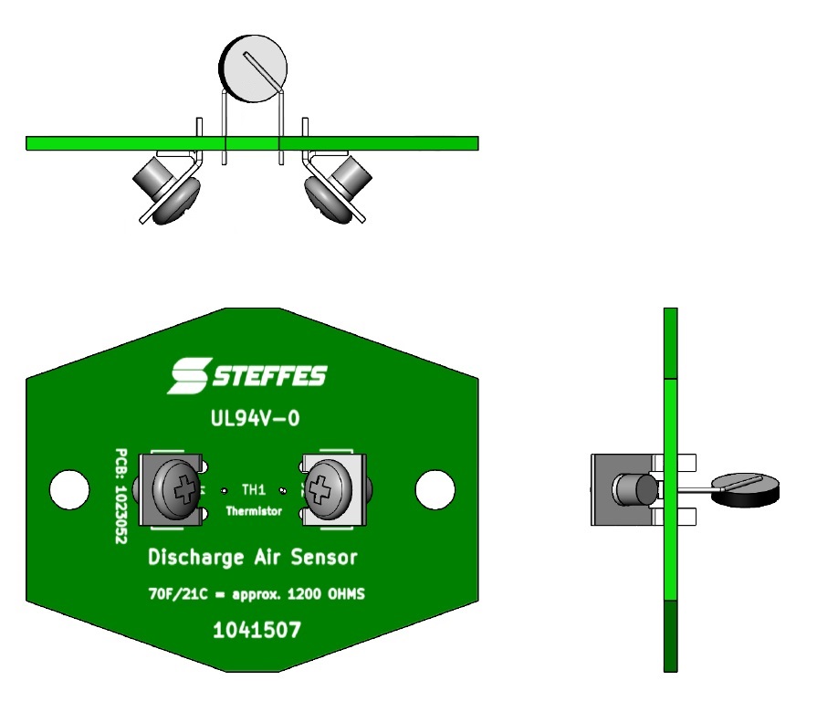
Discharge Air Sensor
|
Model |
Item # |
|---|---|
|
4210 |
1041507R |
The discharge air sensor is located at the top of the supply air blower assembly near the supply air blower limit switch. The processor control board uses this sensor to monitor discharge air temperature and regulate the variable voltage output to one or both of the core blowers to maintain a constant, comfortable outlet temperature.
The system maintains either of two discharge air temperature targets. The lower temperature is Location 48 (L048/C010), which is factory set at 90°F/32°C and the system will target this setting any time there is a Stage 1 heat call and the heat pump is not locked out. If there is a Stage 2 heat call or if the heat pump is locked out for any reason, Serenity will target a discharge air temperature of 120°F/49°C as set in Location 49 (L049).
The discharge air sensor is wired to the low voltage expansion board. The two yellow discharge air sensor wires run from the air handler to the quick disconnect terminals under the circuit breakers and then over to the low voltage expansion board terminals marked "AS". A reading below 25°F or above 175°F will be indicated at the processor control board by a display of Er04 (Error 4, see flowchart).
To test the discharge air sensor, disconnect one yellow wire and take an ohm reading across the sensor and compare it to the Temperature Sensor Resistance Graph and the value in Location 112 (L112). The value in Location 112 indicates the current discharge air temperature as read by the processor control board.
The Serenity is the first to use the green PCB-style discharge air sensor. Terminals are 6-32 screws and on all of these sensors conformal coating has been applied for protection against the environment and cleaning the sensor should not be necessary or effective. This sensor is interchangeable with 1041536R used in other forced air products and accessories.