Part 55 Description - 4100 Series
Discharge Air Sensor
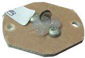
The discharge air sensor is located at the top of the supply air blower assembly near the core blower limit switch and the supply air blower limit switch. This sensor monitors discharge air temperature to help maintain a constant, comfortable outlet temperature.
The minimum discharge air temperature is set in Location 48 (L048). From the factory, this temperature is set to 90 degrees. The system will target a discharge air temperature of 90 degrees any time there is a Stage 1 heat call when utilizing the Comfort Plus with a heat pump. If there is a Stage 2 heat call or if the heat pump is locked out for any reason, the Comfort Plus system will target a discharge air temperature of 120 degrees as set in Location 49 (L049).
The discharge air sensor is wired to the processor control board. The two yellow discharge air sensor wires run from the supply air blower assembly to the 9-pin connector that connects the supply air blower to the furnace. From the 9-pin connector, the two yellow wires route into the electrical compartment. Inside the electrical compartment, the yellow wires are connected to brown wires from the low voltage harness from the processor control board. An open or shorted discharge air sensor will be indicated at the processor board by a display of Er04 (Error 4).
To test the discharge air sensor, take an ohm reading across the sensor and compare it to the Temperature Sensor Resistance Graph and the value in Location 112 (L112). The value in Location 112 indicates the current discharge air temperature as read by the processor control board.
