Part 23 Description - 3100 Series
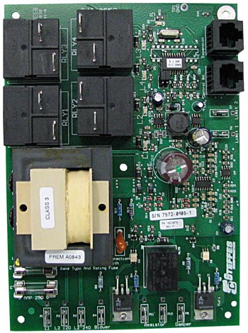
Base I/O Relay Board
The base I/O relay board is utilized within the system to provide power to the processor control board and the internal controls of all circuit boards in the system. The base I/O relay board receives commands from the processor control board to power outputs including the heating elements, supply air blower, and core blower(s). Line voltage power comes into the system at the base I/O relay board. The board is configured with a multi tap input; therefore, L1 is the common terminal, L2 120 is for 120 volt systems, and L2 240 is for 240 volt systems.
NOTE: DO NOT apply voltage between L2 120 and L2 240!
The base I/O relay board also acts as the power line carrier (PLC) receiving device for the heater. PLC signal is read by the base I/O relay board and digital information is sent to the processor control board. In most cases, PLC problems at the heatin system level would be caused by the base I/O relay board.
There are two fuses on the base I/O relay board. The 1/4 amp fuse (order item #1024036) provides power to all of the circuit boards in the system. Line voltage power is current limited through this fuse. Input voltage to the system can be verified by reading voltage AC from L1 to L2 120 or L2 240. Control voltage on the board can be found by reading voltage DC between the Limit 2 (P7) and chassis ground. This voltage should be 10-11 volts DC. If this fuse is open, the system's display will not operate. This input is protected with M.O.V. circuit protection; therefore, a high voltage surge, incorrect input voltage wiring, or a base I/O relay board problem can cause the fuse to open. For troubleshooting information refer to the Base I/O Fuse Open flowchart.
The 5 amp fuse (order item #1024037) on the base I/O relay board protects the variable voltage (triac) outputs for blower and damper control. These outputs pass voltage from the L1 terminal to the blower and damper output terminals. If this fuse is open, the most probable causes would include a shorted blower, a short in the blower wiring, or a shorted limit switch.
To test functionality of the base I/O relay board outputs, power down the system at the breaker. Place the J1 and J2 jumpers in the "on" position (both pins covered with connector). Energize the system and the board will begin a self-test. When in this mode, all outputs will cycle high then low. Therefore, the element relays will close and open, the supply air blower will ramp up in speed then back down, and power to the core blower will be turned on and off. If the board fails this test, it must be replaced.