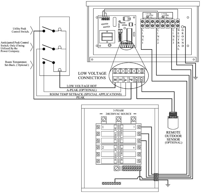
3-Phase Systems Only
NOTES:
-
To ensure proper communications between the PLC transmitter and the controllable electrical loads, the transmitter MUST be grounded.
-
The system grounding and bonding must be sized and installed in compliance with all applicable codes.
-
The transmitter in this diagram is shown connected directly to the service panel. However, any appropriately sized uninterrupted branch circuit can be used to power the transmitter.