The now obsolete Steffes Override Modules are optional devices that allow the use of a normally controlled device, such as a water heater, during a peak control time (power company permitting). Either override timer will allow for an override of the relays. The override duration is 90 minutes (1.5 hours). It can be cancelled anytime during the cycle.
There are two electronic override controls available to use with the transceiver. The push-button override switch, (1), and the three zone override module, (2).
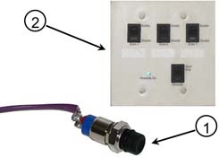
Push-Button Override Switch
-
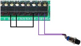
When using the push-button override switch, connect the two purple override wires to the OVR and OVS terminals on the transceiver board’s low voltage terminal block.
-
Connect a jumper wire from OVC to OV1 to override relay #1 and/or from OVC to OV2 to override relay #2.
NOTE: Refer to the Relay Operation section for more information on which relays will utilize the various override inputs.
3-Zone Override Module (1302060)
NOTE: This override module is obsolete as of 7/31/2022.
-
Mount the module into a 2-gang box anywhere in the structure where it will be convenient for the user to access.
-
If using the 3-zone override module, remove applicable transceiver knockout(s) from the bottom of the enclosure below the low-voltage connection area.
-
Connect wires to low-voltage terminal circuit connection points to match circuit leads marked on override module circuit board (OVS to OVS, OVR to OVR, etc.). Tighten terminal screws securely.
-
The module contains five (5) low voltage wires: 3 purple, 1 yellow, 1 red, and 1 orange/black. Splice 18/6 low voltage wire to these wires and route them through the low voltage raceway compartment in the transceiver.
-
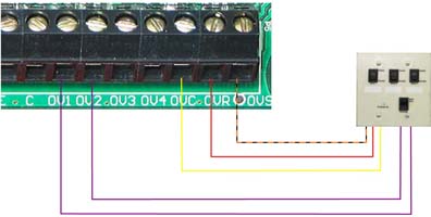
Using only line voltage rated wire inside the transceiver, connect the override to the low voltage terminal strip in the transceiver as follows:
-
Purple wires connect to OV1, OV2, OV3, or OV4 terminals
-
Red wire connects to OVR terminal
-
Orange/black wire connects to OVS terminal
-
Yellow wire connects to OVC terminal
-
-
Label each override zone on the module and in the relay panel (inside, on the front cover label).
-
Install the front cover on the transceiver and energize the system.
Operating the 3-Zone Override Module
-
The module is marked with three separate zones: Zone 1, Zone 2 and Zone 3. These zones correspond to the relays in the transceiver. To enable the override module, press the Override Start/Stop rocker switch once. The green indicator “Override On” light will illuminate.
-
To activate the override of a zone, press the zone(s) rocker switch(es) to the “Enable” position.
NOTE: Zone 1, 2 or all three can be enabled at the same time in any sequence. The light on the 3-Zone Override Module corresponds to LED4 in the Transceiver.
-
To deactivate the override of a zone, press the zone(s) rocker switch(es) to the “Disable” position. The override period can be cancelled by pressing the Override Start/Stop rocker switch again.
Testing the 3-Zone Override Module
-
Initiate a peak mode. Check voltage between T1 and L2 positions of the main wiring terminal block on those circuits connected to the override. There should be no voltage present on any of the circuits.
-
Activate the override by pressing the Start/Stop rocker switch once. Press the rocker switch for Zone 1 to the “Enable” position.
-
Test voltage between T1 and L2 positions of the main wiring terminal block on those circuits connected to Zone 1 Override. There should be a voltage reading. Press Zone 1 rocker switch to the “Disable” position.
-
Follow steps 1-3 to test voltages of those circuits connected to Zone 2 and Zone 3 of the override as well.