THIS PROCEDURE MUST BE PERFORMED BY A QUALIFIED TECHNICIAN.
 WARNING
HAZARDOUS VOLTAGE: Risk of electric shock. Can cause injury or death. Heater may be connected to more than one branch circuit. Disconnect power to all circuits before servicing.
NOTE: It is recommended that the time clock settings are reviewed prior to installation to ensure they are correct for the application. It they are not, follow the steps in the time clock setting instruction sheet.
Disconnect Power
Disconnect power to all branch circuits of the heater.
Remove Front Panel
Remove the front panel of the heater.
Determine Heater Voltage
Check the heater’s identification label on the left side panel to determine its control circuit voltage. Make sure the clock is the same voltage.
Mount Control Board in Service Position
Remove the control circuit board mounting plate by sliding it off its mounting screws. Hook it on these same screws using the eyelet’s provided on the front of the mounting plate for ease of service and access to the wiring compartment.
Mount Time Clock Bracket
Mount the time clock bracket with the screws provided in the kit through the factory pre-drilled holes on the lower right side portion of the control circuit board mounting plate. If the holes have not been pre-drilled at the factory, you will need to drill these in the field.
Mount Time Clock
Be sure the time clock is set correctly. Mount it to the bracket by sliding the top groove on the back of the clock over the bracket. Push down on the bottom front side of the time clock to secure it into place on the bracket.
Wire COnnections
Wiring Connections are as follows:
-
Connect one of the black/yellow wires supplied in the kit to the "L" terminal on the top front side of the time clock.
-
Connect the other black/yellow wire supplied in the kit to the "N" terminal on the bottom front side of the time clock.
-
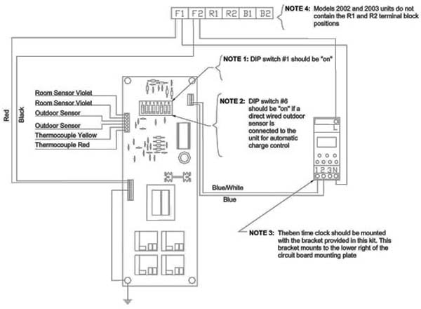
Now connect the black/yellow wires from the "L" and the "N" time clock terminals to the F1 and F2 terminal block positions in the heater if installing in a direct wired unit or to the L1 and L2 terminal block positions in the heater if installing in a 120V plug-in cord unit. These wires can be connected in any order to these terminals.
-
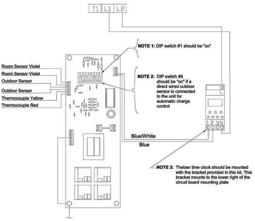
Connect the blue and the blue/white wires of the heater’s control circuit board low voltage harness to the "1" and "2" terminal positions on the bottom front side of the time clock, in any order.
Set Dip Switch #1
DIP Switch #1 on the control circuit board MUST be set to the "ON" position.
Reassemble the Heater
Reassemble the heater by reversing the disassembly procedure.
Restore Power
Restore power to the heater.
Wiring Diagrams
Units with 240V umbilical cord (direct wired) connection:
Units with 120V plug-in cord connection: