All 2100, 2000, and 1000-Series room heaters are factory equipped with a built-in room temperature sensor. This sensor is installed on the inside right side panel of the heater, near the floor. When installing the remote room temperature sensor, the built-in sensor MUST be disconnected. The remote sensor then provides room temperature information to the heater.
The sensor can also be used with Steffes Connect compatible Transceivers to report indoor temperature.
NOTE: For INDOOR use only.
Sensor-to-Wall Installation:
- Remove the cover of the remote room temperature sensor by turning the screws partially in using the 1/16" Allen wrench provided.
- Using the provided mounting screws, attach the sensor to the wall. Optimal wall placement is on an interior wall where it will not be affected by sources of heat or cold.
- Using 2-conductor, low voltage wire (20 AWG minimum for runs up to 50 feet), make the connections to the remote sensor’s two-position terminal(s).
- Reattach the sensor cover and run the low voltage cable(s) from the sensor(s) to the transceiver or heater(s).
NOTE: The wire way through the wall MUST be sealed adequately. Failure to do so may affect the accuracy of the remote room temperature sensor. .
- Test resistance across the field wires routing from the remote room sensor to each heater. Compare the ohm value to the temperature on the Temperature Sensor Resistance Graph.
Sensor to Control/Heater Connections
Transceiver
-
Disconnect power to the transceiver and remove front cover.
-
Route room temperature sensor field wires through the low voltage raceway in the transceiver.
-
Remove thermistor from low voltage terminal block (Figure 2), if applicable.
-
Connect sensor wires to IS and TC (Figure 2) on the low voltage terminal block.
-
Replace the front cover and restore power.
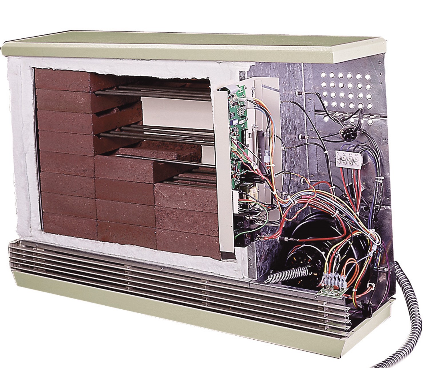
2100-Series
-
Disconnect power to all branch circuits of the heater.
-
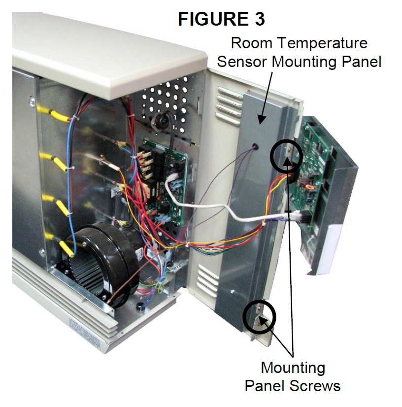
 Remove the front panel of the heater and hinge open the right side panel as shown in Figure 3.
-
Remove the room temperature sensor mounting panel by removing the two screws along the right side of the panel (Figure 3).
-
Disconnect the purple wires from the two position terminal block attached to the inside of the room temperature sensor mounting panel.
-
Route these wires to the low voltage raceway in the back of the heater and connect them to the remote room temperature sensor field wires.
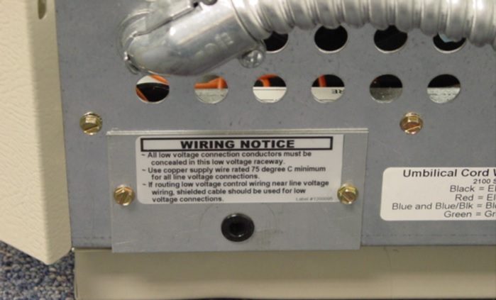
NOTE: NEVER install any wiring in the line voltage electrical compartment of the heater unless it is rated for line voltage.
-
Use the tie wraps provided to bundle the purple wires to the low voltage wiring harness inside the line voltage electrical compartment.
-
Reassemble the heater and restore power. The unit should now display the correct room temperature from the remote sensor. If necessary, use L014 to calibrate the reading on the unit.
1000/2000 Series
-
Disconnect power to all branch circuits of the heater and remove the front painted panel.
-
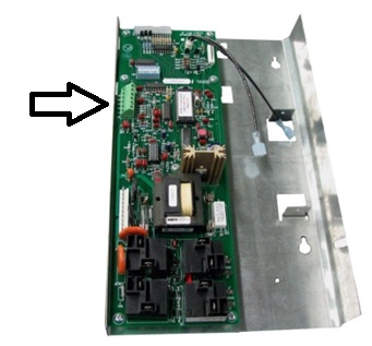
Remove the control board mounting plate by sliding it off its mounting screws and place it into service position.
-
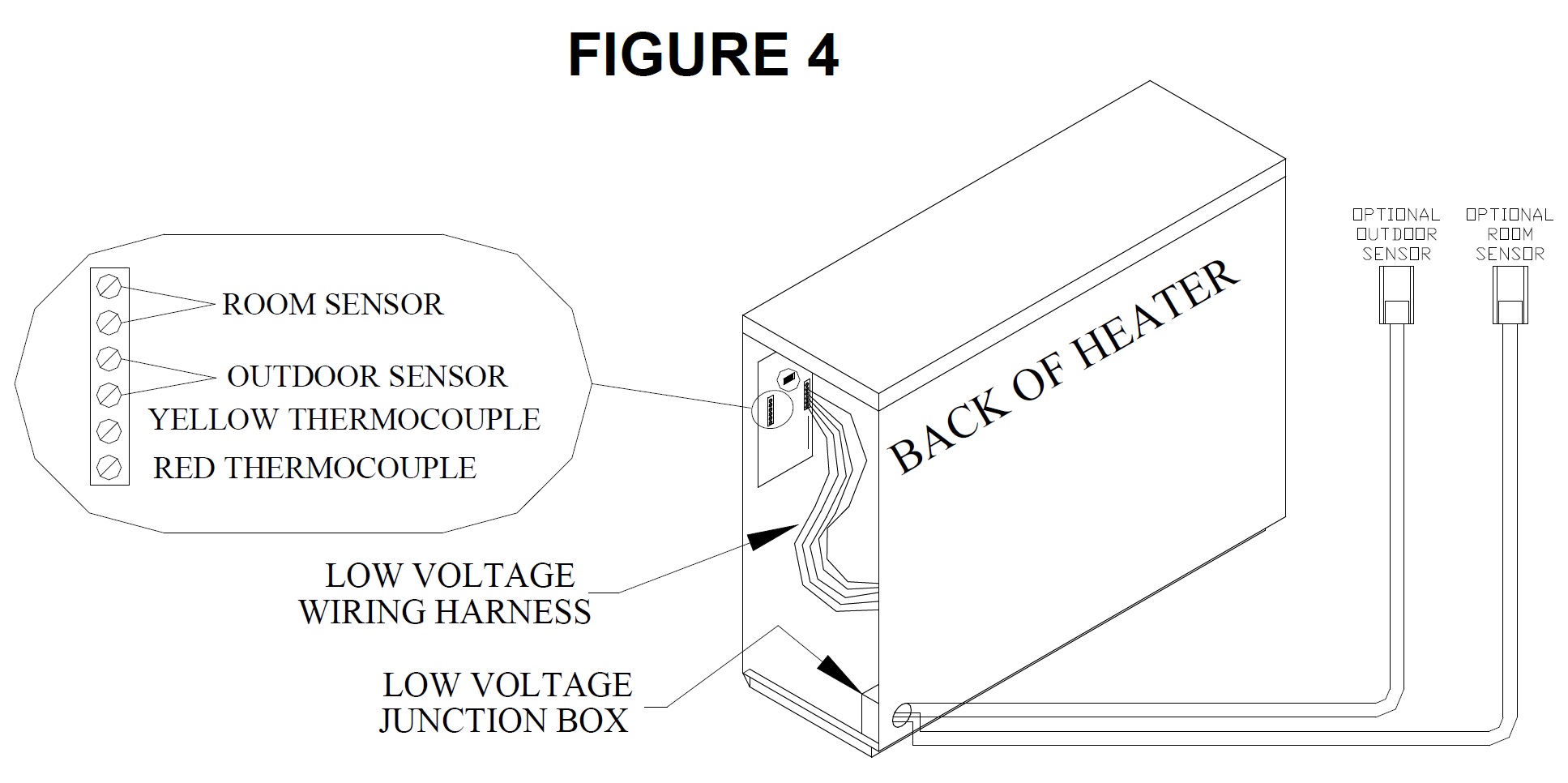
On the back side of the control board, locate the six position terminal strip. Disconnect the built-in temperature sensor by removing the two purple wires in the room sensor (two upper) positions (Figure 4) on the terminal strip and insulate them.
-
2000 Series: Remove the low voltage junction box cover. This cover is located on the lower back side of the heater’s electrical compartment.
NOTE: Do NOT install wiring in the line voltage electrical compartment of the heater unless rated for line voltage.
-
Route the low voltage wire from the remote room temperature sensor to the low voltage junction box (2000 Series) or to the black grommet in the lower back side of the heater (1000 Series).
-
Two (2) pieces of purple line voltage rated wire (39” each) are provided with the sensor. Connect these wires to the room sensor positions of the terminal strip where the two purple wires for the built-in sensor were removed.
-
Route these wires through the heater’s electrical compartment to the field wires and make internal-to-external wiring connections. Use tie wraps provided to secure wires to the low voltage wiring harness inside the electrical compartment.
-
Reassemble the heater and restore power.
 WARNING
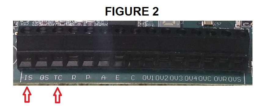
