Six Pole Configuration
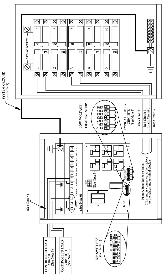
NOTE 1: For more information on the DIP switches, refer to the DIP Switch Settings .
NOTE 2: Mini receiver configuration must be specified at the time of factory order.
NOTE 3: The mini receiver operates on 120V or 208V/240V, single phase. In the single and double pole configuration mini receivers, line voltage connections must be made in the terminal block to configure it to the voltage input being connected to. The six pole configuration mini receiver is factory configured to operate on 208V/240V. If connecting it to 120V, the line voltage connections in the terminal block must be reconfigured and L1 must be the ungrounded leg.
NOTE 4: All line voltage wiring in this device must remain below and in front of the line voltage barrier inside the mini receiver enclosure.
NOTE 5: In the 6-pole mini receiver, circuit 1 feeds both output circuit 1 and the mini receiver’s internal controls.
NOTE 6: With the 6-pole mini receiver, loads connected between L1 & L2 on circuit 1 will be uninterrupted. Loads connected between T1 & L2 on circuit 1 will be interrupted.
NOTE 7: Circuit 1 maximum fuse size is 20 amps. Maximum load is 16 amps. Any loads requiring greater than a 20 amp circuit MUST never be connected to circuit 1.
NOTE 8: Circuits 2-6 maximum fuse is 30 amps. Maximum load is 24 amps.
|
Maximum Fuse Size (6-pole) |
Total Input Circuit Ampacity (6-pole) |
|---|---|
|
Circuit 1 = 20 AMP (16 AMP Load, Max) Circuit 2-6 = 30 AMP (24 AMP Load, Max) |
Surface Mounted = 120 AMPS Flush Mounted = 80 AMPS |
NOTE 9: To ensure proper communications between the PLC Mini Receiver and it’s correlating transmitter, the mini receiver MUST be grounded. The system grounding and bonding must be sized and installed in compliance with all applicable codes.