Single Pole or Double Pole Configuration
NOTE: This Device MUST be Grounded. Grounding and Bonding is not shown in this Diagram.
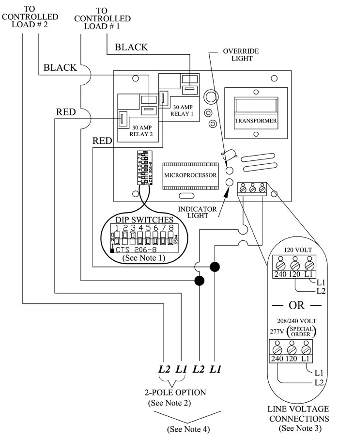
NOTE 1: For more information on the DIP switches, refer to the DIP Switch Settings.
NOTE 2: Mini receiver configuration must be specified at the time of factory order.
NOTE 3: The mini receiver operates on 120V or 208V/240V, single phase. In the single and double pole configuration mini receivers, line voltage connections must be made in the terminal block to configure it to the voltage input being connected to. The six pole configuration mini receiver is factory configured to operate on 208V/240V. If connecting it to 120V, the line voltage connections in the terminal block must be reconfigured and L1 must be the ungrounded leg.
NOTE 4: All line voltage wiring in this device must remain below and in front of the line voltage barrier inside the mini receiver enclosure.