I.E. - Steffes S Series and most European Models
-
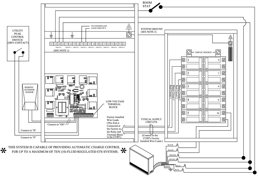
Loads connected between L1 and L2 on circuit 1 will be uninterrupted. Loads connected between T1 and L2 on circuit 1 will be interrupted. CCRP circuit 1 feeds both output circuit 1 and the panels internal controls. Maximum fuse size is 20 amps.
-
The system grounding and bonding must be sized and installed in compliance with all applicable codes.
NOTE: A panel label is provided in the package of screws used to mount the front panel. Apply this label to the service panel to identify the breaker feeding CCRP circuit 1.