Utilizing PLC Control with the Steffes 1000/2000/2100 Series Room Units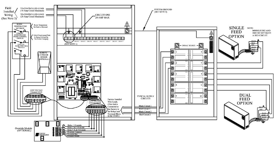
-
Loads connected between L1 and L2 on circuit 1 will be uninterrupted. Loads connected between T1 and L2 on circuit 1 will be interrupted. CCRP circuit 1 feeds both output circuit 1 and the panels internal controls. Maximum fuse size is 20 amps.
-
The system grounding and bonding must be sized and installed in compliance with all applicable codes.
-
Any loads requiring greater than a 20 amp circuit, such as a water heater, must never be connected to circuit 1 in the CCRP as circuit 1 is only capable of controlling a maximum of a 20 amp circuit.
NOTE: A panel label is provided in the package of screws used to mount the front panel. Apply this label to the service panel to identify the breaker feeding CCRP circuit 1.