THIS PROCEDURE MUST BE PERFORMED BY A QUALIFIED TECHNICIAN.
 WARNING
HAZARDOUS VOLTAGE: Risk of electric shock. Can cause injury or death.
-
Do install ducting before energizing Serenity.
-
Do NOT operate Serenity without ducting installed to both the air inlet and outlet.
-
Proper duct design and air flow are critical to achieve optimum system performance. A poorly designed duct system and/or improper air flow can cause system inefficiencies, air noise, and condensate drain problems. In applications where poor air flow conditions exist along with high humidity, it may be necessary to install a secondary condensate drain pan.
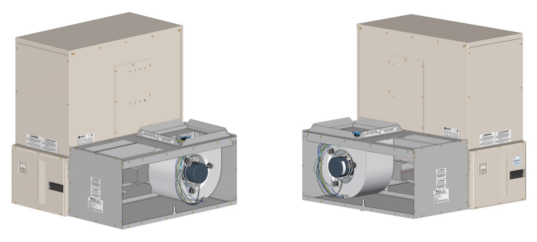
Serenity is equipped with a variable speed supply air blower for air delivery. When interfacing with a heat pump, the A-Coil MUST be placed on the return air side. Static pressure should not exceed 0.75 inches water column.
Serenity is factory configured for a right side air handler configuration but can also be installed with the air handler on the left. In either airflow direction, the house blower must be installed at the rear of the air handler assembly.
Unbox
Unbox the air handler assembly.
Determine Location
Determine which side of Serenity the air handler will be installed - to the left or the right of the heating system.
- The air handler is configured from the factory for right side. If the air handler is to be installed on the right side, proceed to Step 12 (▼).
- If the air handler is to be installed on the left side of Serenity, proceed to Step 3 to swap right and left side air channel components.
Note: Open View for Reference Only
Left Air Handler: Remove Painted Side
Remove the left base painted side panel and galvanized air channel stop (Figure 10).

Figure 10
Left Air Handler: Move Bracket and Scoop
Move the air handler support bracket and air deflector scoop (Figure 11) from the right side to the left side.
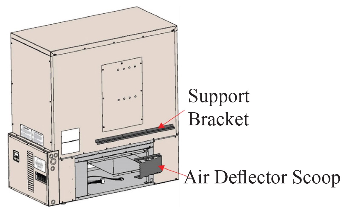
Figure 11
Left Air Handler: Install Stop and Panel
Secure the galvanized air channel stop and base painted side panel to the right side of Serenity.
Left Air Handler: Remove Screws
Remove the screws holding the top panel of the air handler in place.
Left Air Handler: Remove Extension
Remove the extension bracket (Figure 12) by removing the two screws which secure the bracket to the supply blower assembly.
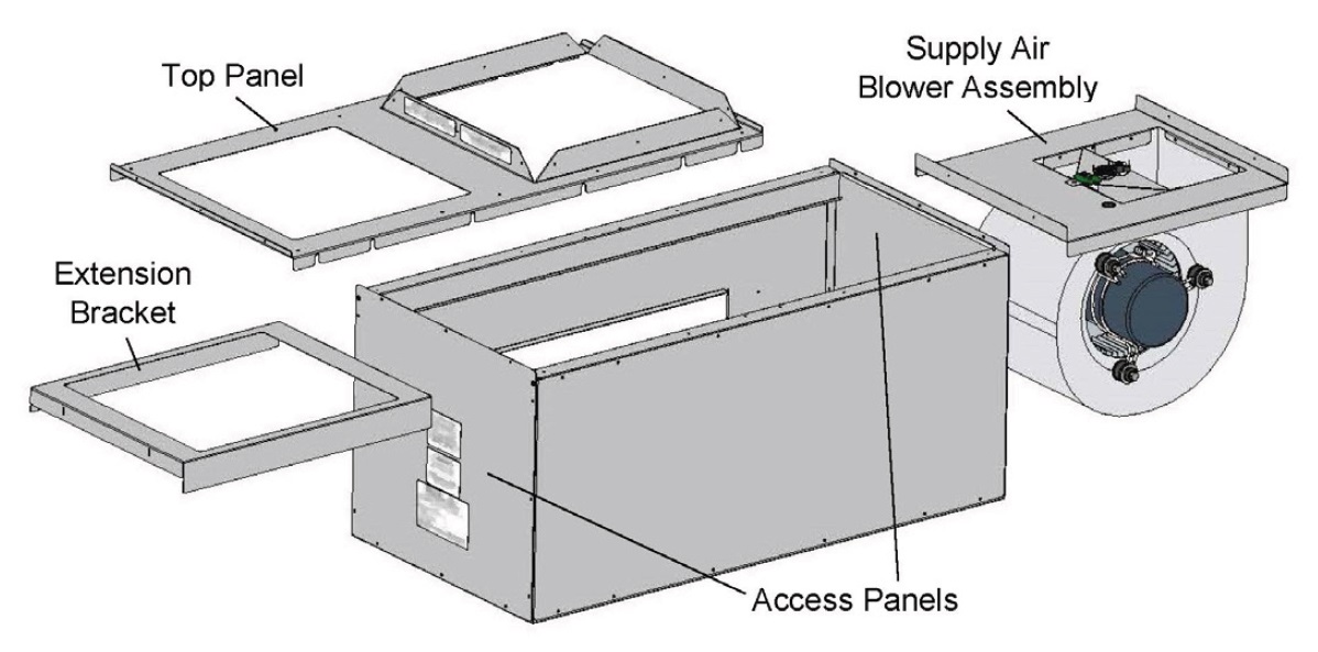
Figure 12
Left Air Handler: Position Air Handler
Position the air handler so the inner side panel is facing the left side of Serenity.
Left Air Handler: Install Blower
Slide supply air blower assembly to the back of the air handler.
NOTE: The supply air blower MUST be placed to the rear of the heating system with the blower motor facing away from Serenity. If the supply air blower is installed incorrectly, it will cause improper air flow.
Left Air Handler: Install Extension
Reinstall the extension bracket in front of the supply air blower assembly.
Left Air Handler: Attach Top
Attach the top panel of the air handler, flanged side up and to the back of the air handler, and secure with screws previously removed.
Remove Access Panel
Remove front air handler access panel.
Determine Location
Slide the supply air blower assembly and extension bracket out of the air handler and set aside.
Route Harnesses
Locate the supply air blower harnesses in the base of Serenity and move them to the side of Serenity the air handler will be installed on.
Position Air Handler
Position air handler to the side of Serenity.
Attach Air Handler
Attach the air handler to the heating system by sliding the flanged edges (sides and bottom) of the air handler into the base of Serenity as shown in Figure 13.
NOTE: Verify the air handler is pushed back to secure the back flange to Serenity. This secures the gasketing around the duct opening. If the supply air blower is installed incorrectly, it will cause improper air flow.
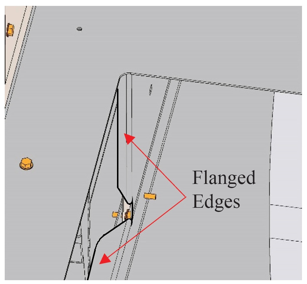
Figure 13
Adjust Leveling Leg
Adjust leveling leg (Figure 14) as needed.

Figure 14
Install Drive
Slide the drive cleat into place as shown in Figure 15.
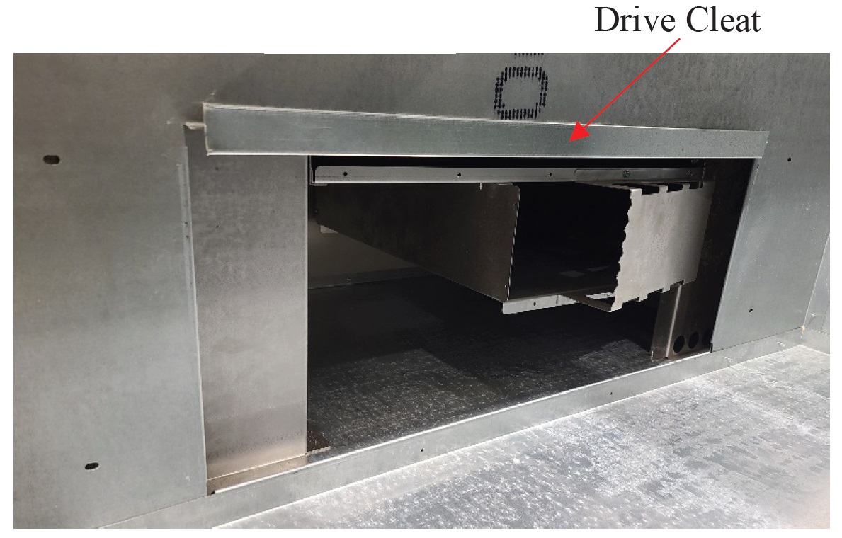
Figure 15
Secure Air Handler
Secure the front of the air handler to the heating system using the two (2) screws provided.
Reinstall Blower
Reinstall the supply air blower and extension bracket by sliding them back into the air handler.
NOTE: The supply air blower MUST be placed to the rear of the heating system with the blower motor facing away from Serenity.
Connect Harness
Attach the 16-pin wiring harness to the bottom of the blower motor. Slide motor forward for easier access to connections.
Connect 2nd Harness
Secure the 9-pin harness from the system to the 9-pin connector towards the back of the motor.
Check Blower Position
Verify the supply air blower is positioned to the rear of the air handler taking care that no wires have been pinched.
Install Cover
Reinstall the front access panel of the air handler.