THIS PROCEDURE MUST BE PERFORMED BY A QUALIFIED TECHNICIAN.
For non-current PSC Supply Air Blowers, click here: PSC Supply Blower Installation
THIS PROCEDURE MUST BE PERFORMED BY A QUALIFIED TECHNICIAN.
For non-current PSC Supply Air Blowers, click here: PSC Supply Blower Installation
For air delivery, the Comfort Plus is equipped with a variable speed supply air blower. When interfacing with a heat pump, the A-Coil MUST be placed on the return air side.
To maintain a room temperature of 85°F/ 29°C or less in the mechanical room, a 24" x 24" opening can be installed in the area or a 6" x 6" non-closing register can be cut into the return air duct. Refer to Placement and Clearance Requirements for more information.
The 4100 Series is factory configured for a left-to-right or right-to-left airflow. In either airflow direction, the holes directly above the air outlet on the right side of the 4100 Series MUST be contained in the duct system. (See Figure 8 for reference to these air holes.)
If a down flow configuration is desired, a down flow kit must be ordered from the factory (Order Item #1301578) and the system MUST be raised a minimum of 10" off the ground. An 18" pedestal is available (Order Item #1301585) to elevate the Comfort Plus.
 WARNING
HAZARDOUS VOLTAGE: Risk of electric shock. Can cause injury or death.
Do install ducting before energizing the system.
Do NOT operate the Comfort Plus without ducting installed to both the air inlet and outlet.
Proper duct design and air flow are critical to achieve optimum system performance. A poorly designed duct system and/or improper air flow can cause system inefficiencies, air noise, and condensate drain problems. In applications where poor air flow conditions exist along with high humidity, it may be necessary to install a secondary condensate drain pan.
Unbox the supply air blower plenum assembly.
Remove and discard metal plate securing supply air blower to plenum assembly.
Locate the plenum support bracket shipped in the plenum box. Attach the bracket to the supply air side using the blunt tip screws supplied. Refer to Figure 8 for proper positioning of the plenum support bracket.
Attach the supply blower wiring harness located in the base of the system to the blower. Place any excess wiring in the base of the system below the radiant heat shield (Figure 8).
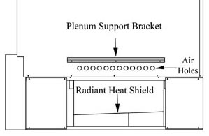

Figure 8: Supply Air Plenum Attachment
 CAUTION
When routing the harness to the supply air blower, the harness must route to the side of the air deflector in the bottom of the supply air blower housing.
Verify that the blower is installed in the plenum with the motor facing away from the system (Figure 9).
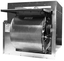
Figure 9
Attach the supply air blower plenum to the Comfort Plus by drilling two 1/8” holes per edge and using the self tapping screws supplied in the hardware package.
Connect both the return air and supply air ducting systems in the structure to the Comfort Plus system. Be sure the air holes just above the air outlet on the right side are contained in the duct system. (See Figure 8 for reference to the location of these holes).
Connect the supply air duct in the structure directly to the system's air outlet located on the top panel.
Adjust the CFM setting at the variable speed low voltage circuit board as shown in Figure 10.

Figure 10
NOTE: External static pressure should not exceed .75 inches water column.
With 2 stage Heat Pump, a Stage 1 heat call results in 70% of selected CFM.
The W/E jumper (Figure 10) MUST be in the ON position or the blower will not operate with an E call from the thermostat.
4100 Install Guide 1206147 Rev 0