THIS PROCEDURE MUST BE PERFORMED BY A QUALIFIED TECHNICIAN.
Item #1023067R - Relay Expansion 8 Relay Replacement Board
THIS PROCEDURE MUST BE PERFORMED BY A QUALIFIED TECHNICIAN.
Item #1023067R - Relay Expansion 8 Relay Replacement Board
 WARNING
HAZARDOUS VOLTAGE: Risk of electric shock. Can cause injury or death. Heater may be connected to more than one branch circuit. Disconnect power to all circuits before servicing.
Disconnect power to the heating system.
Remove the electrical panel cover and locate the relay expansion board(s).
Disconnect the interface cable(s) from the expansion board(s) being replaced.
Disconnect the wires from L1 and L2 240.
Disconnect the wires for the elements, labeling their positions on the board.
Remove the existing relay expansion board(s) by removing the five screws.
Verify J1 and J2 jumpers (Figure 1) are in the correct positions for the application.
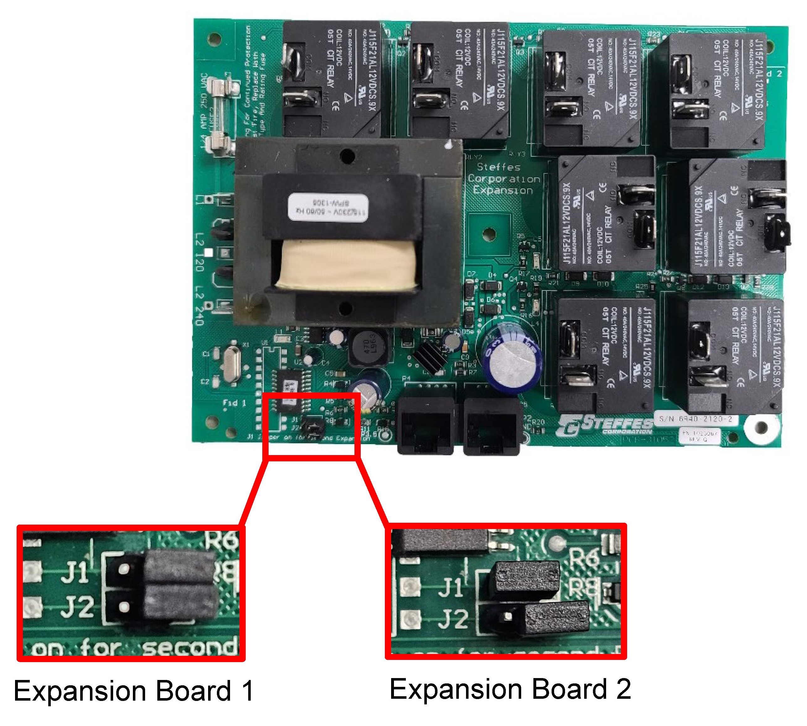
NOTE: Models 3120, 4120, or 5120 only have one relay expansion board; therefore, jumpers 1 and 2 MUST both be OFF.
Models 4130, 4140, 5130, and 5140 have both a first and second relay expansion board. Verify the top relay expansion board is configured as expansion board one and the bottom relay expansion board is configured as expansion board two.
Mount the new relay expansion board(s) using the screws previously removed.
Connect the wires to L1 and L2 240.
Connect the element wires back in the same positions as on the original board.
Connect the interface cable(s).
Reinstall the electrical panel cover and energize the system.
Ensure proper operation by completing the Installer’s Final Check-Out.
Verify the value in Location 40 (L040).
|
Unit |
L040 Value |
|---|---|
|
3100 Series |
1000°F / 537°C |
|
4100 Series |
1200°F / 648°C |
|
5100 Series |
1200°F / 648°C |
Instruction 1209009 Rev 6 03/12/2025