THIS PROCEDURE MUST BE PERFORMED BY A QUALIFIED TECHNICIAN.
WARNING

HAZARDOUS VOLTAGE: Risk of electric shock. Can cause injury or death. DO NOT energize the heater until installation is complete. Equipment must be installed by a qualified technician in accordance with applicable local, state, and national codes and regulations.
Risk of fire. Can cause injury or death. Poor or marginal electrical connections will cause the connections to overheat and fail. Use extreme caution when making all electrical connections.
Configuration
In standard configuration, the charging circuit of the heater is wired for connection to 240V or 208V. The blower and controls circuit in the heater is configured for 240V or 208V (special configuration changes needed for 208V, see next paragraph). In standard configuration, Steffes heaters are dual rated for 240V and 208V power connections. The heaters are factory configured for 240V. If the control circuit is to be connected to 120V, please contact the factory to order this special configuration.
208V Note:
If connecting to 208V, the heating elements will operate at 75% of their rated wattage (contact the sales department to understand the impact on heating capability). If the blower and controls circuit is operating at 208V, the value in Location 16 (L016) must be changed to 210 and the value in Location 28 (L028) must be changed to a value of 5 for heaters equipped with a Fasco blower or a value of 10 with a P-Tech blower.
Field Connection Wire and Circuit Breaker Sizing Guide
All 2100 series heaters are equipped with a two-circuit element feed option and a fan/control circuit.
Refer to one of the following diagrams:
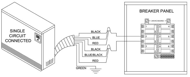
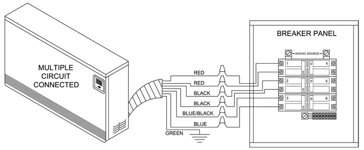
Determine Circuit Size
Refer to the Unit Identification Label on the heater for proper sizing of each circuit (example label). If single-feed connection is used, size the circuit for total wattage (Charge Crct #1 + Charge Crct #2 + Fan/Cntrl Crct = Total Wattage). Refer to the Wire and Circuit Breaker Sizing Guide for more information.
Mount Junction Box
Mount a field connection junction box either beside or behind the heater or mounted in the floor below the heater. The junction box MUST remain accessible for future service to the heater and MUST be sized in accordance with all applicable electrical codes and regulations.
Route Wires
Route the proper size and type of wiring from the breaker panel to the field connection junction box. Use copper wire rated at 75°C minimum only.
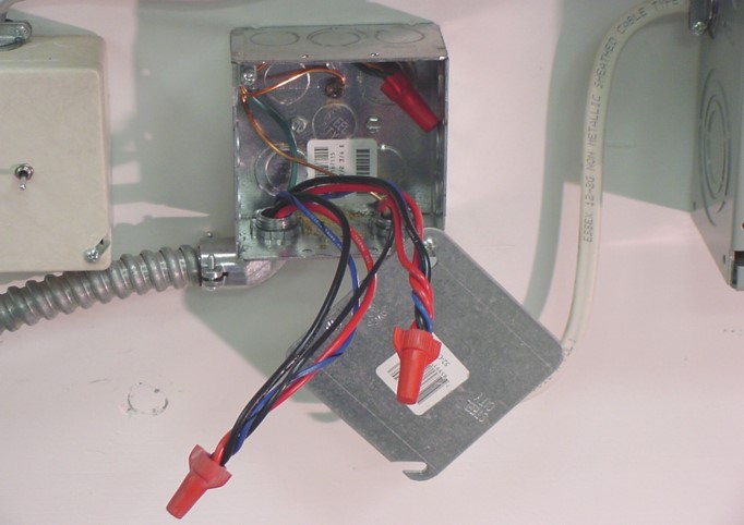
Connect Field Wiring
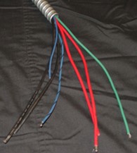
Connect the field wiring to the wiring harness (umbilical cord) of the heater inside the junction box.
Label Electrical Panel
Remove the orange breaker panel label from the mounting hardware package. This label MUST be applied in the electrical service (breaker) panel and marked accordingly to identify the branch circuits feeding the room heating unit.