THIS PROCEDURE MUST BE PERFORMED BY A QUALIFIED TECHNICIAN.
 WARNING
HAZARDOUS VOLTAGE: Risk of electric shock. Can cause injury or death. Heater may be connected to more than one branch circuit. Disconnect power to all circuits before servicing.
Description
Element failure is generally caused due to an overheating of the brick core. Therefore, if elements have failed, it is important to find what the root cause might be. Following are steps for verifying system operation
Route from the Brick Core to the Processor Control Board
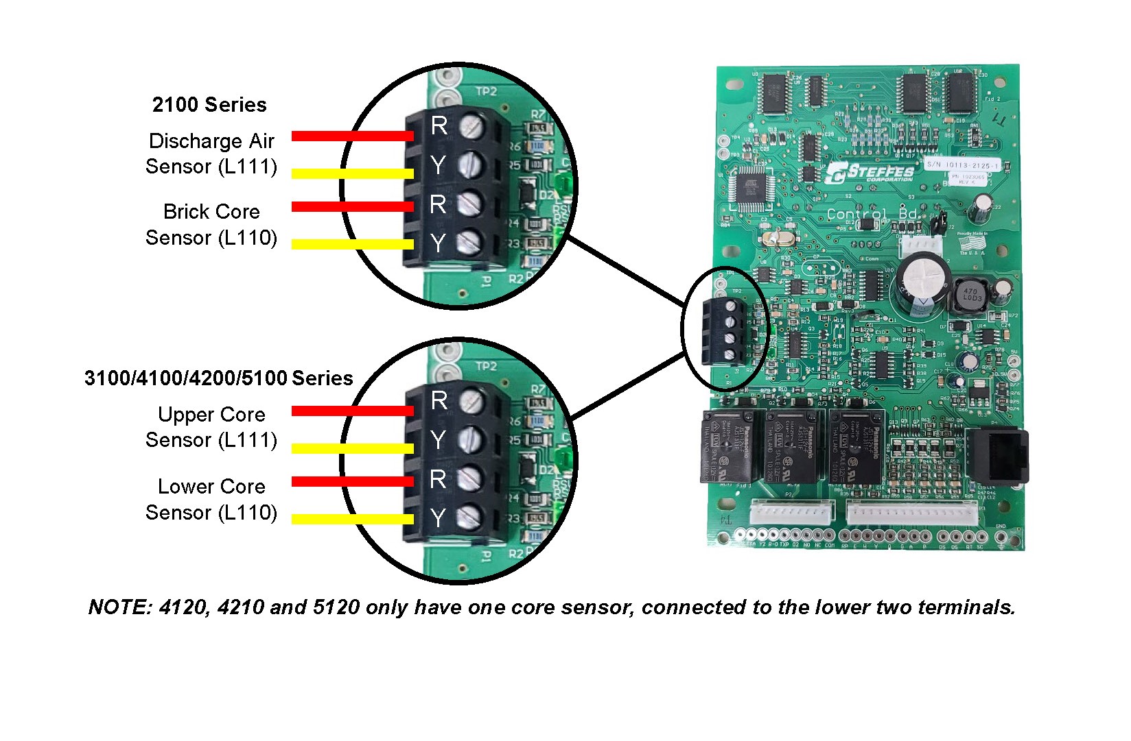
- 3120/4130/4140/5130/5140 Series: These heating systems have two core temperature sensors. The upper core temperature sensor must be connected to the top two ports on the 4-position terminal block and the lower core temperature sensor must be connected to the bottom two ports on the 4-position terminal block.
-
2100/4120/4210/5120 Series: These heating systems only have one core temperature sensor. This sensor must route to the lower two ports on the 4-position terminal block
Connecting the Core Temperature Sensor(s) to the Processor Control Board
- Core temperature sensor(s) are k-type thermocouples and are polarity sensitive. Verify the core temperature sensor(s) are connected as shown below. The red wire goes to R and the yellow wire goes to Y.
-
Verify there is no insulation caught in the connections
-
Do a pull test on the wires. A loose connection will cause the temperature readings to be inaccurate and to fluctuate.

Testing the Core Temperature Sensor(s)
NOTE: The core temperature sensors in the Model 3120 cannot be removed.
- Remove the brick core temperature sensor(s) from the core. Use caution when doing so as they may be hot.
-
Heat the end of each thermocouple up with a torch. While doing so, watch L110 for the lower core temperature sensor and L111 for the upper core temperature sensor. As the sensor heats and cools, the temperature shown in L110 and/or L111 should gradually go up and down.
-
When the tip of the core temperature sensor is glowing red, the temperature in L110 and/or L111 should be approximately 1,200°F/648°C.
Processor Control Board:
To verify that the processor control board knows how to read core temperature accurately, replace the core temperature sensor(s) with copper jumper(s).
- With a copper jumper in place of the lower core temperature sensor, L110 should show 60°-90°F/15°-32°C with an ambient room temperature of 70°F/21°C.
-
With a copper jumper in place of the upper core temperature sensor, L111 should show 60°-90°F/15°-32°C with an ambient room temperature of 70°F/21°C.
-
If the temperature readings are outside of this range, contact Steffes Technical Support.
Relay Expansion Board(s)/Base I/O Relay Board:
- After replacing any failed elements, verify that all of the elements turn on when the heating system is placed in a charge mode and a charge control override is activated.
-
Verify that all elements turn off when the heating system is placed into a peak mode.
Location 40 (L040):
- If a heating system has had element failure, it is possible that the system has also had a Core Fail Error message at some time. With Core Fail, the system will decrement the value in L040 by 50°F/10°C.
-
Check Location 40 (L040) and make sure it is at the factory default for the heating system being repaired. See the Supplemental Installer's Guide for more information